Als auch die Japaner bei Edel-Hifi mitspielten . . . .


. . . . mußten sie die Geräte auch ausmessen und die Qualtät bewerten und evtl. verbessern. Die Großen wie SONY, Matsushita usw. hatten eigenen High-End- Labors und "machten" sich auch ihre eigenen "Prüfmittel".
Der kompetente Meßingenieur (es gibt bei den Ingenieuren einen ganz spezellen Fachbereich und auch einen ganzen Studiengang "Meßtechnik") lernt das alles. Der Fachbereich ist zwar in der Regel getrennt nach Elektronik und Mechanik, doch beim analogen Plattenspieler (und auch beim Tonbandgerät) ist unbedingt beides miteinander zu betrachten und zu verknüpfen.
Der angehende Ingenieur und speziell der Meßingenieur lernt gleich in den ersten Semestern, daß für aussagekräftige Beurteilungen das Meß-Equipment immer mindestens Faktor 10 besser sein muß !! als das zu messende Objekt (also der Proband), immer !!. Sonst sind die Messungen mehr zufällig und nicht vergleichbar.
Und natürlich gab es das Wissen auch in Japan und in Korea.
Das erstaunliche daran ist für uns, die bei weitem besten Meßgeräte kamen zuerst nicht aus dem eigenen Land, sie kamen aus Dänemark, Deutschland und USA.
Auf dieser Meßschallplatte von Technics (Panasonic) sind auch die einzelnen Geräte aufgelistet, mit denen erstens die Referenzen erzeugt wurden (also Mikrofone und Bandspeicher) und mit denen die verbliebene Qualität am Ende der Kette gemessen wurde.
Das Cover gefunden, die Platte nicht gefunden
Die Platte selbst ist in irgend eine andere Hülle reingerutscht und im Moment nicht verfügbar, aber die Suche geht weiter. Die Informationen auf dem 4seitgen Cover sind aber bereits sehr aussagekräftig.
.
Technics AUDIO TEST RECORD SFC-TR100


Progress in audio technique and stereophonic reproduction equipment during the last few years has been quite remarkable. Precise evaluation of performance, therefore, requires programs having superior sound characteristics and tone quality.
The more excellent the characteristics of the phonograph equipment, the more necessary it is to have a high quality test record that can fully measure its performance to guarantee quality.
This audio test record, which guarantees the high performance of the Technics 100C series phono cartridge, has been produced with a Side-A for use in meausuring the specifications and a Side-B which enables you to check the pick up and audio system while enjoying classical music.
This ultra high quality test record is necessary for measuring high quality cartridges. On Side-A, signals for measuring or checking the basic specifications of the pick-up and the audio system are recorded. The test record has the unique features of enabling one to check the specifications of the pick-up by listening to the record as well as using measuring equipment.
Precautions (Vorbereitung)
The drive of the cutting lathe has been precisely adjusted and controlled by a quartz-locked oscillator so that lock-steady speed accuracy has been maintained. Furthermore, the cutting system has been dramatically improved at low frequency response and calibration of the recording level has been made by simultaneously employing the multi speeds and Buchmann-Meyers light pattern methods which enable us to produce a high quality test record with improved cutting accuracy of the frequency response.
The result is that the superb cutting accuracy has been obtained making it possible to correctly measure the fundamental characteristics of pick-ups and audio systems, such as output voltage, frequency response and crosstalk characteristics etc. Bands 1~5 are cut at half speed (16-1/3 r.p.m.) and band 6 is cut at 5 times normal speed (166 r.p.m.).
Contents of Side A
| Band 1: | Reference signal at 1kHz | (0:10) |
| Band 2: | Sweep frequency from 40Hz to 20kHz. | (1:40) |
| Band 3: | Spot frequencies | (2:24) |
| Band 4: | Amplitude sweep at 1kHz and 100Hz for tracking ability check | (1:08) |
| Band 5: | White noise for channel balance and phasing check | (0:32) |
| Band 6: | Low frequency sweep from 4Hz to 100Hz for the tonearm resonance check | (2:30) |
Contents of Side B
Three images by "Chaconne (J.S.Bach) BWV 1004 " arranged by Doyo Kono
| 1. PART I | (8:29) |
| 2. PART II | (3:58) |
| 3. PART III | (3:15) |
.
On Side-B, classical music specially arranged to obtain a wide range of sound and natural tone quality, is a depature from the conventional type of test record with enriched content for your listening pleasure. In addition recording techniques of the highest standard available, such as employment of the most up-to-date recording facilities and equipment and use of a special record manufacturing process adopting a new blend of phono disc materials, etc., have been utilized to produce this record. The tape recorder is always operated for recording and reproduction at double speed (76cm/sec).
.
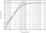
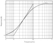
- Fig.1 Recording Characteristics and Specifications (Band 2-5)

How to use
Band 1: Reference signal
1kHz reference signal is recorded. Recording level is 5cm/sec, zero to peak, lateral (JIS standard). Output voltage, channel balance and signal to noise ratio can be measured by this band.
- Anmerkung : Die Erklärung für den "JIS Standard" fehlt noch.
.
| Frequency | Velocity (zero to peak) | Tolerance (dB) | Tolerance (dB) |
| Hz | cm/sec 45° | Left channel | Right channel |
| 62.5 | 0.56 | -0.2 | -0.3 |
| 125 | 0.92 | 0.0 | -0.1 |
| 250 | 1.61 | 0.1 | 0.2 |
| 500 | 2.51 | 0.1 | 0.2 |
| 1000 | 3.17 | 0.0 | 0.0 |
| 2000 | 3.42 | 0.1 | 0.0 |
| 4000 | 3.51 | 0.0 | 0.1 |
| 8000 | 3.53 | -0.2 | 0.1 |
| 16000 | 3.54 | -0.1 | 0.1 |
Zur obigen Tabelle : Speed accuracy: ±0.01% - Frequency accuracy : Sweep Frequency: ±1% - Spot Frequencies: ±0.001%
.
- Fig.2 Recording Crosstalk Characteristics (Band 2-5)

Band 2 .Sweep frequency from 40Hz to 20kHz for frequency response check
Sweep frequency from 40Hz to 20kHz, left and right channels are recorded for the measurement of the frequency response, crosstalk and harmonic distortion using a level recorder. The recording characteristics and crosstalk characteristics are shown in Fig.l (1/2 RIAA recording curve) and Fig.2.
The sweep speed and start signal (1kHz, lateral) are synchronized to the B&K response test unit 4409 or 4416 and the B&K level recorder 2305 with a paper speed of 3mm/sec.
The equalization curve for the purpose of reproduction is shown in Fig.3-a when the B&K measuring equipment is not available.
.
Band 3: Spot frequencies
Spot frequencies, left and right on alternate channels at "16kHz, 8kHz, 4kHz, 2kHz, 1kHz, 500Hz, 250Hz, 125Hz and 62.5Hz" make it possible to measure the characteristics of the cartridge without using a level recorder. The recording characteristics and level are the same as band 2. (Refer to Fig. 1).
Note:
1kHz left channel spot signal is interrupted in a moment. This is used as a start signal in case of automatic recording.
.
Fig 3: Suggested Playback Equalizer :
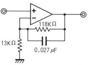
- Fig. 3-a: Equalizer for Bands 2 and 3

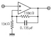
- Fig. 3-b: Equalizer for Band 6

.
Band 4 : Amplitude sweep at 1 kHz and 100Hz for tracking ability check
This band is for the measurement of the tracking abilitycheck of a cartridge. In the case of the conventional test record, (wie auf den bei uns bekannten DHFI Testplaten von Karl Breh enthalten) it takes a long time to measure the critical tracking force by increasing or decreasing the tracking force during the measurement. Also it cannot measure the real tracking ability under the normal tracking force.
While in this test record, the amplitude or recording level of the cutting signal is swept in accordance with the time. It is, therefore, easy to check the tracking ability by finding out the time when sound is distorted under the normal tracking force.
.
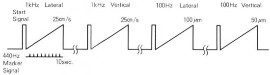
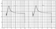
- Fig.4 Amplitude - Sweep of Band 4

As shown in Fig.4, the amplitude sweep lateral and vertical signal of 1kHz is recorded from zero to 25cm/sec (±14dB) maximum velocity for the high frequency tracking ability check.
The amplitude sweep signal of 100Hz is recorded from zero to 1OOum maximum amplitude for lateral and from zero to 50um maximum amplitude for vertical. These bands are cut with an especially high level, that is, with the maximum cutting level of the cutter head.
The amplitude sweep continues for 10 seconds after 1kHz pilot signal is heard. 440Hz marker signal of one second interval each, is also recorded. (See Fig.4). The mechanical impedance at 1 kHz and the compliance at 100Hz can be meamured by counting the time when the sound is distorted or rattled. The mechanical impedance and compliance of cartridge can be measured according to Figs.5 and 6 respectively.
.
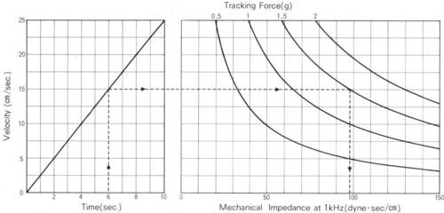
- Fig.5 Tracking Ability Check and Mechanical Impedance Measurement at 1kHz (Band 4)

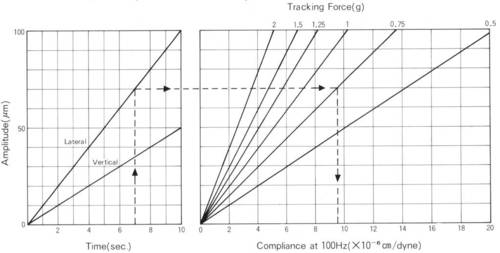
- Fig.6 Tracking Ability Check and Compliance Measurement at 100Hz(Band4)

Note:
1. These bands are recorded with the maximum amplitude level of the cutting limitation. Therefore, it may be almost impossible for a cartridge to trace all the modulated grooves perfectly.
- Anmerkung : Der Neumann Schneidkopf war das Feinste auf der Welt, und der konnte immer deutlich mehr als die besten Abtaster jemals abtasten konnten. Nicht umsonst hatte die Neumann Schneid-Maschine 2 x 500 Watt Sinus Treibervestärker für die Schneid-Stichel-Technik.
2. Please do not use the heavy tracking force type of cartridge. It may cause wear of the specially modulated grooves.
- Anmerkung : Gemeint ist hier, benutzen Sie für diese Testplatte nie die vom Hersteller spezifizierte maximale !! Auflagekraft. Das zerstört die Rille(n).
.
Band 5: White noise for channel balance and phasing check
The white noise of left channel, right channel, both channels in-phase and out-of-phase are recorded for the channel identification, channel balance and phasing check.
Note :
The sound image should be located at the centre of the two loud speakers using the both channels in-phase signal.
.
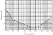
- Fig.7 Recording Characteristics of Band 6

- Fig.8 Typical Low Frequency Responce Using Band 6

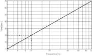
- Fig.9 Tonearm Resonance Measurement (Band 6)

Band 6: Low frequency sweep from 4Hz to 100Hz for tonearm resonance check
Low frequency sweep, left and right channels, from 4Hz to 100Hz are recorded for the measurement of the tonearm resonance frequency. 1kHz pilot signal is also recorded with 440Hz marker signal of one second interval each. After 1kHz start signal, the low frequency sweep begins. Recording characteristics are shown in Fig. 7.
A response chart as shown in Fig.8 is attained corresponding to the paper speed of 1mm/sec on the B&K 2305 level recorfer using the same equalization shown in Fig.3-b. This band is recorded at 5 times normal speed (166-2/3 r.p.m.).
1kHz pilot signal is continuously recorded at a smaller level in order to recognize the resonance frequency (fo) by ear. When listening carefully to the 1kHz pilot signal, you can hear the signal modulated at the resonance frequency area. By counting the marker signal when the resonance occurs, you can determine the resonance frequency (fo) according to Fig.9.
If it is difficult to identify the 1kHz pilot signal modulated, it may be possible to find out the resonance frequency area by noticing the point of the maximum woofer flutter.
Note:
1. The groove between band 5 and band 6 dose not continue.
2. The pitch of the lead-out groove dose not meet to the standard pitch. Therefore, the tonearm may not return automatically even when using an automatic turntable.
.


Approximate locations in the recording hall and our use of equipment
| Recording_and_playback_equipment | |
| • Mixing console | ADM Model 2824 |
| • Level mixer | VUE SCAN |
| • Multi-track tape recorder | AMPEX MM-1200 |
| • Track down tape recorder | AMPEX ATR-102 |
| • Tape | AMPEX "GRAND MASTER 456" |
| • Echo machine | EMT 240 |
| • Monitor speaker | JBL 4331, Technics SB-7000, ALTEC 604E |
| • Cutting head | NEUMANN SX-74 |
| • Cutting lathe | NEUMANN VMS-66 |
| • Amp rack | NEUMANN SAL-74 |
| • Play back tape recorder | STUDER A-80 |
| • Monitor speaker | Technics SB-7000, ALTEC 604E |
| • Equalizer | Technics SH-9090P |
| • Monitor turntable | Technics SL-1000 MKII |
| • Monitor cartridge | Technics EPC-100C, 205C-IIL |
| • Monitor amplifier | Technics SE-9060, SU-9070, SE-9600, Mcintosh MC-2100 |
| . | |
| Microphones | |
| M1 | NEUMANN U-87 x 2 |
| M2-M6 | NEUMANN M49B |
| M7 | NEUMANN U-87 |
| M8 | SCHOEPS CMC50 |
| M9-11 | NEUMANN M269 |
| M12-M13 | NEUMANN U-87 |
| M14 | AKG D24 |
| M15 | SCHOEPS CMC50 |
| M16 | AKG 452 |
| Ml7 | NEUMANN U-87 |
Imprint / Impressum
| Promotion director: | Shuichi Obata (chief), Tadashi Abe | |
| Producer: | Masaaki Onuki | |
| Mixing engineer: | Akio Yamazaki | |
| Assistant engineer: | Hidemi Hattori | |
| Maintenance engineer: | Katsumi Okamoto | |
| Cutting engineer: | Senzo Shiomi (chief), Shuichi Sakaguchi | |
| Conductor/arranger: | Doyo Kono | |
| Recorded at: | Teichiku Suginami studio, Tokyo | |
| Produced by: | Teichiku Records Co. Ltd. | |
| Overall planning: | Stereo Dept. Matsushita Electric Industrial Co., Ltd. |