"Wide Range Electrostatic Loudspeakers" (3)
- QUAD ESL 57

By Peter. J. WALKER (Acoustical Manufacturing Co., Ltd.)
Wireless World, August 1955
3. Complete Systems
Loudspeaker-Room Relationships
.
In the first part of this article we showed that for a given size, the apparent efficiency of an electrostatic unit may be increased by reducing the bandwidth which that unit is required to cover.
An obvious method of increasing the overall efficiency of a complete electrostatic system, therefore, is to divide the system into a convenient number of frequency bands and to feed them via crossover networks. Optimum-design is obtained by increasing gaps and areas with decreasing frequency.
An alternative method of increasing apparent efficiency is to subdivide the loudspeaker area into a number of smaller units each covering the whole frequency range, the units being coupled by inductors so that the whole loudspeaker becomes a transmission line. (Fig. 1.)
The acoustic radiation resistance
The acoustic radiation resistance appears as conductance in parallel with each capacitive element. For a fixed total area, and neglecting losses, the efficiency varies directly with the number of subdivisions.
Consideration of these two systems shows that frequency division has considerable advantages over transmission line divisions for most complete systems of domestic size and power requirements.
First, if a single nine-octave unit is subdivided into a two-unit system, the apparent efficiency is increased 16 times. To obtain the same increase by transmission line division would require a minimum of 12 divisions.
Unless the total area of the loudspeaker is large, and the plate separation small, the capacitance of each section of the transmission line becomes very small indeed and requires correspondingly large inductance which must be of relatively high "Q".
This apparent efficiency advantage of frequency subdividing over transmission line dividing holds until the bandwidth of each unit is reduced to two octaves.
Also doch nach Frequenzbereich aufteilen
Apart from transmission line subdivision applied to individual units of a frequency-divided system, practical consideration normally limits transmission line techniques to large-area diaphragms.
When such is the case, however, additional facilities are available to the designer both in the accurate control of directional characteristics and in providing a constant phase contour, independent of frequency.
In discussing various possible forms of complete electrostatic systems, a novel situation arises. The quality criterion of a loudspeaker usually concentrates on three performance parameters, as measured in an unlimited atmosphere,
- (a) Ability to produce a required sound intensity over the audio spectrum with negligible non-linearity distortion,
- (b) The sound pressure over the designated listening area should be independent of frequency throughout the audio range,
- (c) Operation should be aperiodic.
Complete loudspeakers designed on the principles which we have been discussing are capable of meeting these three requirements to a new and exciting degree. We shall see that different designs and approaches differ not so much in terms of (a), (b) and (c) above, but in other factors of importance to quality reproduction; factors which have previously had to take second place or have been masked in the struggle for (a), (b) and (c).
.
Corner Mounting
There has been a strong tendency in loudspeaker design to make use of the corner of a room. This is because at low frequencies the air load resistance for a given size of diaphragm is increased 8 times over that of an unlimited atmosphere.
Since the ratio of cabinet "stiffness" to air load resistance is independent of diaphragm size, any increase of resistance due to boundary walls and floors fundamentally reduces the size of cabinet required for a given performance.
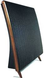
As an example, the form of corner electrostatic loudspeaker illustrated in Fig. 2 and designed for full performance down to 40c/s utilized an internal resonance with a "Q" of 3 and a built-in enclosure of 10 cu ft.
Fundamentally the enclosure size could be reduced either by
- (1) increasing "Q",
- (2) reducing power and apparent efficiency requirements, or
- (3) restricting frequency range.
Any one factor may be traded for any or all of the others.
Den Fußboden mitbenutzen
It should be noted that with the diaphragm area of Fig. 2 the resistance could be substantially increased by reshaping the whole of the low-frequency area near the floor so that, with the boundary reflections, its dimensions laterally and vertically are similar.
Such a form, with a suitably shaped treble unit above it, can be designed to give a level response in direct radiation to the listening area, so that the (a), (b), (c) requirements are not affected.
Homogeneity on the other hand, due to the physical spacing of units, is destroyed. This may be more important than is generally realized, particularly in rooms of normal domestic size.
The high-frequency section (centre strip in Fig. 2) is sealed at the rear by an enclosure of width equal to that of the strip and incorporating a fibreglass wedge to offer almost pure resistance throughout the range of the unit.
This sealing is necessary in order to maintain front air load resistance by preventing coupling between front and back.
Eine andere Form der Plazierung in einer Ecke
Fig. 3 shows an entirely different form of corner design. The diaphragm area covers the whole surface and extends around the back to form an enclosed cylinder. Every part of the diaphragm carries the whole frequency range. The surface area is divided into units to form a transmission line. The total volume is 15 cu ft.
The step in diameter is introduced because the transmission line rotates around the top portion and thence around the bottom portion. The time delay in the sound expanding from the top portion to the diameter of the bottom portion is equal to the time delay of the electrical voltages in the transmission line.
The complete assembly is placed a small distance from the corner of a room so that the boundary reflectors are aiding at the lowest frequency of interest. The large diaphragm area together with the boundary reflections provide a loading approximately equal to pc at 30-40c/s.
Eine Grenzfrequenz von 400 Hz
Internally there is acoustic resistance treatment, so that there will be resistive loading at high frequencies, changing to a capacitive load due to the lumped enclosure at low frequencies. Simplified equivalent circuits for high and low frequencies are shown in Fig. 4.
The turnover occurs at about 400 c/s and it is obvious that with constant voltage the response will be level above 400 c/s and drop at 6dB/octave below this frequency. This is corrected by progressively rematching to the amplifier below 400 c/s. The section shape may be elliptical to give a degree of direction at high frequencies.
It is obvious that the corner boundaries will introduce peaks and troughs throughout the frequency range. These are, however, exactly the same as occur naturally with live speech or music originating near boundaries in a room. To what degree these effects are important must at the present time be a matter of conjecture. It can safely be said that the subjective effect is by no means as alarming as the appearance of the response curve.
Die Nachteile der "Ecke"
The advantage of a corner position has already been noted. This advantage is not gained without considerable detriment in other directions. If we wished to excite every room resonance to its fullest extent with a sound source of high internal impedance, we put this source in a corner because this is the position of highest impedance for every mode.
In placing our loudspeaker in a corner therefore we are placing it in the worst possible position if our aim is smooth aperiodic sound.
Although the present trend appears to be to tolerate this state of affairs in the interest of the organ's 32ft rank (or reduction of cabinet size), the inherent smoothness of electrostatic loudspeakers once experienced is not lightly thrown away, and there is added impetus in attempts to improve the loudspeaker/room relationship.
Double Wall Enclosure
The strip "twin" unit design of Fig. 2 may be built into a wall in such a way that most room modes are not excited or are excited only feebly. If it is an outside wall, the rear enclosure may be added externally. If an inside wall it may spread over the wall so that from the appearance point of view it has virtually disappeared.
Fig. 5 shows the general form of installation. The strip unit extends from floor to ceiling and the low-frequency sections are backed by 5 inch wide enclosures 4 1/4 ft in length, with fibreglass wedges incorporated.
The impedances and response are shown in Fig. 5 (June issue). With the dimensions of this example, d=10" since both 5" units are coupled, and the response will be within 3dB of 1 kc/s response down to 35 c/s.
These figures include floor, one wall and ceiling, but do not, of course, include the effects of other room boundaries. Assuming a 2" thick wall for rigidity, the volume of a room of 300 square feet floor area would be reduced by 2%.
There can be no initial excitation of floor to ceiling modes because vertical excitation is evenly distributed. Modes excited in a direction parallel to the wall on which the speaker is mounted will be reduced in number. Assuming a rectangular room, the number of modes excited will be some four times less than the number excited by a corner floor position.
So ist wenig Wünschenswertes dabei
As can be seen by the following summary, this form of loudspeaker leaves little to be desired.
- 1. The enclosure being "built-in" can be completely rigid.
- 2. The only fold in the enclosure is narrow compared to wavelength and being close to the diaphragm can cause no reflections in the range of that unit.
- 3. The loudspeaker and its enclosure are completely predictable.
- 4. The (a), (b) and (c) requirements previously mentioned can be met virtually to perfection.
- 5. Radiation throughout the whole frequency range is homogeneous; there is no source displacement and no phase problems at crossover.
- 6. Total radiated energy (as well as axial pressure) is independent of frequency.
- 7. The loudspeaker/room relationship is good.
.
Item 6 deserves further mention. The normal frequency response specification of a loudspeaker is in terms of sound pressure produced on the axis or over a limited listening arc.
The mean spherical radiation (total power output) is not usually specified, although it will have a profound effect in a room because the intensity of indirect sound is dependent upon it. If high-frequency radiation is limited to a segment of, say, 90° x 30° (a typical figure) and bass radiation is hemispherical, and if the axis response is level, then there will be a step of 12dB in the mean radiated response.
This produces an artificial step in the acoustic ratio (ratio of direct to indirect sound) producing unnatural hardening of the reproduced sound.
Doublet Sources - beidseitige Abstrahlung
We now come to consideration of the doublet as a sound source and we shall see that it possesses properties of considerable significance in improving loudspeaker / room relationships. By a doublet we mean a diaphragm, radiating on both sides.
If we assume a 12" - 15" unit (moving coil or electrostatic) mounted in a 4ft-5ft baffle, we find that the acoustic system has three main faults.
- (1) The acoustic air load falls to very low values at wavelengths larger than the baffle size.
- (2) The acoustic load is very irregular at low frequencies and
- (3) reflections from the baffle edge occur at higher frequencies.
The second and third faults can be mitigated by adopting peculiar shapes.
A composite electrostatic unit
If, instead of a baffle, we construct a composite electrostatic unit of the same area, the position is completely altered. The resistance per unit area and the total working area are both increased so that the air load is many times that of the baffle case. The load, and consequently the performance, is regular and predictable.
The construction is that of strip units progressively increasing in plate spacing and area from the centre line. Due to the air load resistances involved for each strip, the permissible bandwidth is reduced over that which could be obtained if the back radiation were sealed off and it is necessary to split the frequency range into three to obtain efficiency comparable to a two-way " sealed " system.
Any unloaded strip considered alone will have a resonant frequency when the diaphragm stiffness reactance equals the air load mass reactance.
This is, however, placed below the frequency range of the strip, so that the mutual radiation of the adjacent strip carrying a lower frequency range increases the radiating area and prevents the application of any effective mass.
Ein beinahe resonanzfreies System
The complete system is therefore entirely free of resonance except at one low frequency (usually placed at 30-35 c/s). The "Q" of this resonance is adjusted to maintain response to this frequency.
The complete loudspeaker has a cosine characteristic and this is substantially maintained through the range. It cannot radiate sound in the direction of its surface, horizontally or vertically, so that it cannot excite room modes in two out of the three room dimensions.
It will only excite modes in the remaining dimension when placed at a region of maximum velocity for that mode. (The impedance looking into the loudspeaker is low.)
Having a "cosine" polar characteristic the mean spherical radiation is reduced by a factor of 3 at all frequencies, so that quite apart from freedom of mode excitations any colour due to the room is reduced by a factor of three.
This is exactly analogous to a "velocity" microphone. In the same way that a "velocity" microphone is used in place of a "pressure" microphone to reduce studio colour, this "velocity" speaker will reduce colour due to the listening room.
Über die Schnelligkeit eines Lautsprechers
Listening tests comparing "pressure" (Schalldruck) and "velocity" (Schnelligkeit) speakers of otherwise similar characteristics indicate that a velocity characteristic may well have important features for high-quality reproduction. An electrostatic loudspeaker of this type correctly positioned in the room meets all requirements as did the "wall" form previously described, with the addition of an even better loudspeaker/room relationship. The fact that it requires to be free standing well within the room may or may not be advantageous.
The more the acoustic ratio is reduced (provided always that it is reduced equally at all frequencies), the more one approaches the state of affairs that the pressure at the ears is a replica of the pressure at the position of the microphone in the concert hall or studio (ideal headphone conditions).
Es spricht viel dafür und viel dagegen
It must be emphasized that many arguments for and against this condition have been proposed. It is outside the scope of these articles to enter these arguments other than to say that with a monaural channel the choice must be an aesthetic one.
A complete listening room can be designed to produce pressures throughout the room which are more or less equal to the pressures at the studio microphone.
A tube of small diameter compared to wavelength fitted with a piston at one end, and terminated at the other by a resistance of pc will give pressures anywhere in the tube which are directly proportional to piston velocity and independent of frequency. Provided that the area of the piston equals the tube cross-sectional area, then the requirement of small diameter disappears.
A rectangular room with a diaphragm covering one wall and correct termination on the opposite wall meets the requirements. The space behind the diaphragm must be at least l0" deep and treated like the speaker in Fig. 3. The equivalent circuit is the same as Fig. 4. The sound absorption treatment of the opposite wall must ideally be several feet in depth.
Sound intensity throughout the room is independent of position (including the distance from the diaghragm). The apparent sound source is always in a direction perpendicular to the diaphragm and, of course, moves as the listener moves.
Und das Ganze jetzt in Stereo
The same loudspeaker may be used for stereophony. With transmission line matching and feeding the signal at one end the wavefront will be tilted, due to time delay. Separate signals may be fed from either end to produce two tilted wavefronts, one for each signal. Since each apparent origin is perpendicular to its wavefront, the aspect angle from the listener is a constant and entirely independent of the listener's position over a large triangular area (Fig. 6). The relative intensity of the two signals is also constant.
A fixed angle, two-channel system of this type may be obtained with a less elaborate listening room. The strip arrangement of Fig. 5 may be installed horizontally instead of vertically. If each unit is a transmission line along its length, then two cylindrical wavefronts will be produced with exactly the same feature of constant aspect angle already described.
Die Zusammenfassung
To summarize, the electrostatic principle is capable of surmounting the present limitations of other methods of drive. It is capable or overcoming the present tweeter/woofer concept to produce a closely coupled, integrated assembly.
The problem of loudspeaker/room relationships (common to all loudspeakers) still remains, although the design versatility of the electrostatic makes it possible to design for optimum relationship if these can ever be defined for a monaural channel.
A closer understanding of the relative importance of the many factors involved are needed.
- (a) Source movement with frequency, movement wiin uequenuy,
- (b) Homogeneity,
- (c) Acoustic ratio,
- (d) Mode excitation,
- (e) Phase contour, etc.
All are factors which can only be tentatively assessed after long usage.
The author wishes to thank Ferranti Ltd. for permission to publish the result of work jointly carried out, and to acknowledge the invaluable work of D. T. N. Williamson, W. D. Olliphant, and their colleagues at Edinburgh. Thanks are due to J. Watson, J. Collinson and others at the Acoustical Manufacturing Company, and to the several specialists who have been able to assist with problems in their own field.
.
geparkte Bildunterschriften
Fig. 1. Capacitive loudspeaker elements coupled with inductances to form a transmission line.
Fig. 2. Widerange electrostatic loudspeaker in a resonant corner enclosure.
Fig. 3. Cylindrical electrostatic loudspeaker. Each strip carries the full frequency range and the sections are coupled to form an electrical transmission line. The inductor assembly is shown below.
Rx FRONT AIR LOAD C, DIAPHRAGM COMPLIANCE
R2 INTERNAL RESISTIVE LOAD C« ENCLOSURE COMPLIANCE
Fig. 4. Equivalent circuits at high and low frequencies of the acoustic loading on the loudspeaker of Fig. 3.
Fig. 5. Sectional plan showing one method of rear enclosure for a strip electrostatic unit.
Fig. 6. Stereophony from a single transmission line loudspeaker, with separate channels feeding each end of the line.
hints :
shape Form / Aussehen
piston = Kolben
baffle = Schallwand
wedge = Stück /Teil / Ecke
transmission line - Schallrückführung durch ein "inverted folded horn"
mr. beveredge elektrostaten
.