"A Low Frequency Horn of Small Dimensions"
(Ein niederfrequentes Horn mit kleinen Abmessungen)
Dr. Paul Wilbur Klipsch - Houston, Texas - (Received August 7, 1941) - Reprinted from The Journal of the Acoustical Society of America, Vol. 13, No. 2, 137-144, October, 1941
Dieser Artikel ist also aus 1941 . . . !!!! , . . .
als der 2.Weltkrieg bereits in vollem Gange war. Und in dieser Zeit schreibt ein Paul Klipsch eine recht lange Abhandlung über die Theorie des akustischen Hornes im Lautsprecherbau. Und er führt extrem detailgenau aus, wie er sich das vorstellt. Der Artikel ist in Englisch. Korrekturen und Anmerkungen von Gert Redlich. Vielleicht finden wir ja mal die deutsche Übersetzung.
-
A new loudspeaker horn is described.
It is a low frequency horn so folded as to utilize wall and floor reflections to improve the impedance match at the mouth. When operated in a room corner, the speaker is capable of reproducing sounds of wave-lengths over 8 times the actual apparatus dimensions with efficiency and smoothness of response comparable to theater "woofers" of several times the size of the device described. Since its size is approximately that of a console radio, it is applicable to living room use. Because of its high efficiency, its use for small theaters and recreation centers is indicated.
With suitable modifications for one or more larger size driving units, it would be capable of delivering the large amounts of power required for large theaters. Units may be stacked or clustered for outdoor use. With a frequency range of 40 to 400 cycles it is capable of fine quality when used with a suitable high frequency unit, and since the high frequency unit needs to deliver power only down to 400 cycles it may be made quite small.
The loading due to the horn offers a high real component of impedance for the diaphragm to work against, resulting in low diaphragm excursion and consequently the generation of negligible harmonic components compared with what would be generated by the same driving unit delivering the same sound output from a flat baffle.
Motional impedance measurements show that the efficiency is good - down to 40 cycles. The use of the corner, which is ordinarily wasted space, and the arrangement of side baffles so that they, together with the room walls, form the terminal section of horn, results in a simple compact structure and a considerable saving in material. In spite of the small size there is no sacrifice in quality.
Introduction
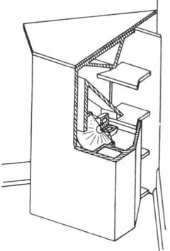
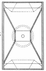
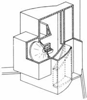
- Fig. 1. Cut-away oblique view of the new horn speaker arranged to take advantage of the high room-corner acoustical impedance.

Many schemes for utilizing the higher acoustical impedance existing in a room corner have been devised.
Kellogg,1) Stone,2) Weil,3) Ephraim,4) Sandeman,5) and Horace-Hulme,6) are representative of the early art. Very recently there has been announced a bass-reflex enclosure designed to fit in a corner.
The present development offers a horn type reproducer of dimensions which are smaller compared to the longest wave-length to be reproduced than has heretofore been possible.
The advantages of the horn are well known. Compared to the direct radiator operating in a flat baffle, the efficiency of the horn is 10 to 50 times higher, and the acoustic loading due to the horn permits a given sound power to be generated with much smaller diaphragm excursions, a factor which greatly reduces harmonic distortion. Well-designed horns are capable of very uniform frequency response. The power handling capacity is high.
Referenzen:
- 1) E. W. Kellogg, J. Acous. 3, 54 (1931).
- 2) Stone, U. S. Patent 1,819,721 (1931).
- 3) Weil, U. S. Patent 1,820,996 (1931).
- 4) Ephraim, U. S. Patent 1,962,300 (1934).
- 5) Sandeman, U. S. Patent 1,984,550 (1934).
- 6) Horace-Hulme British patent, 342,369 (1931).
- 7) Electronics, p. 99 (May, 1941).
-
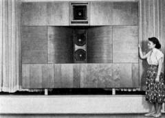
- Ein deutscher Klangfilm Kinolautsprecher

In the past, however, horns for reproducing low frequencies have been very bulky. A typical theater (gemeint ist "Kino") "woofer" occupies a space nearly 4 x 4 x 8ft.
Figure 1 shows a horn unit adapted to fit in a corner. With a frequency response down to 40 cycles, corresponding to a wave-length of 340 inches, comparable to the performance of the typical theater woofer, this unit measures only 39 inches high, about the same width across the "wings" and only 28 inches deep from front panel back to the corner. The cabinet size is comparable with radio consoles and is entirely suitable for use in homes. The power handling capacity is such as to make it adaptable for use in community centers, little theaters and medium size recreation halls. By suitable modification, power handling capacity for large theaters may be attained.
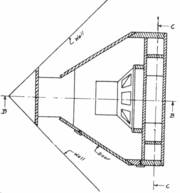
- Fig. 2. Sectional view from the top of the new horn.

To reproduce this wave-length with the same degree of smoothness of throat impedance and the same efficiency, a conventional horn in free space would require a mouth area of about 4.500 square inches. If operated close to a floor or wall, 2.300 square inches would be required corresponding to a circular mouth 53 inches in diameter. The horn length required to match a 15-inch diaphragm would be over 80 inches. The horn of Fig. 1 has an actual mouth opening of 570 square inches and a horn length of approximately 40 inches representing a saving in volume of over 75% and a corresponding saving in material for its construction. A further saving in material results from using the room walls for part of the horn structure.
Description
- Fig. 3. Sectional view from the side.

Figures 2, 3, and 4 show the construction of the unit. Figure 2 is a sectional view showing how the unit is nested into the room corner, and also the arrangement of side baffles, front panel, and driving unit. The side baffles are arranged at such an angle that they, together with the room walls, floor, and cover plate, form the final horn section. Radiation into pi/2 solid angle (due to the reflections from the wails and floor) make the required mouth area only 1/4 as great as would be required for radiation into 2pi solid angle where only the floor is used as a reflector.
Figure 3 is a vertical section through B-B of Fig. 2 and shows the air passages from the diaphragm to the rear of the horn cabinet. The driving unit and an air chamber behind the diaphragm are illustrated. Figure 2 is the section A-A of Fig. 3.
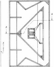
Figure 4 is a section through C-C of Fig. 3 and shows the throat opening from the diaphragm and the first diverging set of baffles.
Multiple Flake
- Fig. 4. Sectional view from the front.

The design illustrated is for a 12-inch driving unit (Anmerkung: das Bass-Chassis). The frequency range is from 40 to 400 cycles. For good diaphragm loading at 400 cycles a throat area of about 50 square inches is about right for a 10.5-inch diameter diaphragm and a moving system weighing between 14 and 18 grams. Such a small throat imposes an unnecessarily high load at the lower frequencies. Consequently, the initial taper is such that the horn area doubles in a length of about 8 inches, corresponding to a cut-off of 100 cycles.
The remainder of the horn flares at such a rate that the area doubles every 16 inches so that the nominal cut-off is 47 cycles. This results in a "rubber throat" the area of which is about 100 square inches up to 100 cycles and decreases with frequency until at 400 cycles the effective throat area is 50 square inches. Except that the initial taper is conical, this idea is roughly the same as that offered by Olson,8) and roughly the same results may be predicted.
Air Chamber Between Cone and Throat
To overcome the positive reactance imposed at the higher frequencies (200 to 400 cycles) by the multiple taper, a negative reactance is introduced by the air chamber of about 250 cubic inches between the diaphragm and the throat. This air chamber is shorter than 1/8 wave-length at 400 cycles.
Air Chamber Behind Cone
The air chamber behind the diaphragm is designed to offset the mass reactance of the throat impedance at low frequencies.
To offset exactly the throat reactance of an infinite horn, the air chamber behind the diaphragm should have a volume 2.9 times the throat area multiplied by the length of horn within which the area doubles. This is readily shown as follows.
The air chamber reactance in mechanical ohms on the diaphragm is :
The throat reactance at cut-off, in mechanical ohms on the diaphragm is:
where Ad = diaphragm area; At = throat area; co = angular velocity at cut-off =2x/ where /is the frequency; 7= volume of air chamber; p = density of air; c - velocity of sound.
To make the two reactances equal, Eqs. (1) and (2) must be equal. Thus,
The length of horn within which the area doubles is :
where Alpha is the longest wave-length to be transmitted, and f is the lowest frequency.
Thus,

In the present design, l=16 inches, Ar=100 square inches, so for the infinite horn, the volume is V=4600 cubic inches.
In a finite horn, the throat reactance fluctuates about a value equal to the reactance of a negative capacitance. The initial peak is so large that theory indicates the air-chamber capacitive reactance for the finite horn should be higher than for the infinite horn. Apparently, the reactance can be from 1.5 to 2 times as great for a horn of the length being considered as for the infinite horn.
The diaphragm suspension stiffness con tributes some to the total, but in the examples tried with 12-inch speakers this constitutes only 15 percent to 25 percent of the stiffness of the enclosure.
Approximately 3000 to 3500 cubic inches is a satisfactory value for the 100 square inch throat. A volume of 2600 cubic inches proved satisfactory in an experimental model with a 70 square inch throat and the same taper. In the design shown the gross volume is about 3900 cubic inches, of which about 600 cubic inches are taken up by the driving unit, its mounting, and the front air chamber.
Since the average distance from the cone to the air chamber surfaces is about equal to a quarter wave-length at 400 cycles (8.5 inches), the first air chamber resonance occurs at this frequency. At resonance the resistive and reactive load on the back of the cone will be very low. For frequencies below 400 cycles the reactance will be capacitive, and below about 100 cycles will differ inappreciably from the value computed from Eq. (1).
Mouth
- Fig. 5. Computed impedances for the new horn. Solid curve, resistive component of throat impedance. Dotted curve, reactive component of throat impedance. Dashed curve, combined effects of stiffness of the back-of-cone air chamber and the mass reactance of the moving system.

The mouth size selected is 570 square inches. This corresponds to an equivalent mouth of 2280 square inches radiating into 2x solid angle. This condition exists when the horn mouth is fitted with a flange or is operated close to a wall or floor.
The horn performance may be computed on the basis of one having an actual mouth area equal to the 2280 square inch equivalent mouth and a length equal to the actual length. This results in the computed throat impedance being that of a throat of 4 times the actual throat area. The mechanical inpedance on the actual diaphragm may be found by multiplying this computed mechanical impedance value by 4. Calling the mouth area 570 square inches is conservative, as that is the horn area at the forward edges of the non-parallel side baffles. The additional taper due to the parallel side portions will undoubtedly reduce the magnitude of the first peak in the throat impedance curve below the computed value.
For an equivalent 100-cycle horn, the mouth area would be (47/100) 2 x 2280 = 500 square inches, the area of a 25-inch diameter circle. Olson (9.) has worked out throat impedance curves for various mouth sizes. This 25-inch mouth is intermediate the 20- and 30-inch mouth sizes, the performances of which are shown in his figures 5.5b and 5.5c, and the horn length corresponds roughly with his Fig. 5.6d.
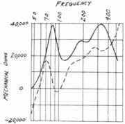
- Fig. 6. The load on the diaphragm due to the combined effects of the horn, the mass reactance of the moving system, and the front and back air chamliers. Solid curve, resistive component. Dotted curve, reactive component.

Thus the impedance curve may'be expected to be somewhat smoother than that shown in his Fig. 5.6d due to the 25 percent larger diameter mouth. A few points were computed and this seems to be the case. The impedance was computed to 200 cycles, and the effect of the multiple taper beyond this frequency was estimated on a basis of Olson's work on multiple flare horns. (8) The results are shown in Fig. 5. The solid curve is the resistive component of the throat impedance in mechanical ohms on the diaphragm. The dotted curve is the reactance in the same units. The dashed curve is the combined mechanical reactance of the diaphragm mass and the behind-the-cone air chamber.
The effect of the air chamber between the throat and the cone can be computed from the equivalent circuit. The combined effect of these factors is plotted in-Fig. 6, in which the solid curve is the resistive component and the dotted curve is the total reactive component of the load on the diaphragm in mechanical ohms. The reactive component includes the horn throat reactance, the cone mass reactance and the effect of both front and back air chambers.
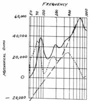
- Fig. 7. Motional impedance at the voice coll computed from the curves of Fig. 6 for a driving unit with a Bl product of 15 X 10G gauss-centimeters. Solid curve, resistive component. Dotted curve, reactive component.

The motional impedance for a driving unit with a product of flux density square times voice coil mass of 550 X106 and a voice coil resistance of 6.5 ohms is plotted in Fig. 7. This impedance is simply
where for a 6.5-ohm coil, B2L2 is 225 x 10 hoch 12 and Zm is the impedance from Fig. 6.
The efficiency computed from this is shown in Fig. 8. The efficiency used is that of Eq. (6) given later in this paper, and takes into account che losses in the driving amplifier. The driving source impedance is 6 ohms.
- 8) H. F. Olson, "A horn consisting of manifold exponential sections," J. Soc. Mot. Pict. Eng. 30, 551 (1938).
- 9) H.F.Olson, RCA Review 1, No. 4, pp. 68 (1937); Also Elements of Acoustical Engineering (Van Most rand, 1940), Figs. 5.5, 5.6, 5.7, 5.8.
-
Experimental Results
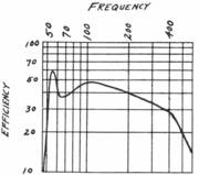
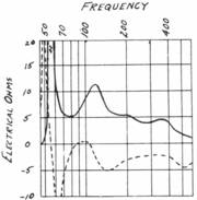
- Fig. 8. Computed absolute efficiency, including consideration of the driving source impedance, based otf computed motional impedance of Fig. 7. Voice coil resistance 6.5 ohms. Power source impedance, 6 ohms.

Figure 9 shows the results of motional impedance measurements which were made on an experimental model. This model was constructed along the general lines just described but differed somewhat in the more complicated and less efficient folding (from the standpoint of conservation of space), and in that the back-of-cone enclosure consisted of a box bolted to the front of the cabinet. The construction of this rather awkward affair is shown in Fig.10.
The experimental model is inferior in many respects to the design described earlier in the paper. Orders to report for active military duty preclude a thorough investigation of the new design. From the computed and experimental results on the experimental model about to be described and from the computed performance of the new design, it may be safely predicted that the actual performance of the new design will be better than for the experimental model.
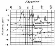
- Fig. 9. Measured voice coil impedance of a driving unit operating in an experimental horn. Solid curves, resistive component. Dotted curves, reactive component. The blocked impedance, or no-motion condition, was obtained by turning off the field supply resulting in curves marked "field off." The differences between the normal and "field-off" curves give the motional resistance and reactance.

The "blocked" impedance measurement was obtained by turning off the field supply. The differences between the pairs of curves give the motional resistance and reactance. There may be some question as to the accuracy of such a "blocked" impedance measurement, but, since the flux from the voice coil has to traverse the air gap twice, it seems that the saturation would have little effect on the static voice coil impedance, especially at frequencies below 1000 cycles.*
-
- * That the diaphragm motion is negligible is amply demonstrated by the fact that the field-off curves of Fig. 9 are smooth and vary only to the extent of showing the effects of self-inductance.
-
The horn was constructed with a single flare instead of a multiple flare from a throat of about 70 square inches to a mouth of 800 square inches. The air chamber between the diaphragm and throat was more or less indeterminate as the driving unit was reversed and the field mechanism occupied part of the air chamber and throat. This, together with complicated folding and the fact that the throat was too large, probably accounts for the low impedance beyond 200 cycles. The side panels were quarter-inch plywood and were not adequately braced; their vibration may account for some of the irregularities from 80 cycles up.
- Fig. 10. Construction of the experimental model; the driving unit is reversed with the rear of the cone facing the horn throat, and the front of the cone closed off by an air chamber of size suitable to offset the reactive component ol throat impedance. Comparison with Fig. 1 shows the simpler, cleaner construction of the new design in which the air chambers are both behind the front panel.

The driving unit was a Jensen 12A with a resonant frequency in free space of 63 cycles. The measured stiffness of suspension when new was approximately 3300 grams per centimeter. The force factor, Bl, or flux density times active length of voice-coil conductor was measured and found to be 1SX106. The voice coil resistance was 6,5 ohms.
From these factors and from horn theory, taking into account the mass reactance of the moving system, the suspension and back-of-cone air chamber compliance, and the horn throat impedance calculated from the dimensions, the motional impedance was computed.
The computed resistive component of the motional impedance is plotted (solid curve) in Fig. 11, together with the rneasured resistive component (dotted curve).
The measured curve indicates better low frequency performance than the computed curve. While there is only a fair agreement between the two curves, it is believed that the discrepancies are explainable. First, the horn theory must be in considerable error in the immediate vicinity of cut-off. (10)
Second, vibration of the thin side baffles can readily cause the peaks and hollows above 80 cycles. Third, the air chamber between throat and cone was of complicated shape and the estimated volume may have been in considerable error, giving rise to error in the computed impedance above 200 cycles.
-
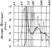
- Fig. 11. Comparison of computed and measured motional impedance of the experimental model; it will be noted that the experimental curve shows performance down to lower frequencies than the computed curve and the measured impedance varies between narrower limits than the computed values. Solid curve, computed resistive component of motional impedance. Dotted curve, measured resistive component of motional impedance.

The cut-off of the horn is 47 cycles and the computations show poor performance below 55 cycles. But the measurements and critical listening tests show good performance down to 40 cycles.
The peaks in impedance above 80 cycles probably do not indicate increased efficiency but rather increased losses due to mechanical vibration of the thin side baffles.
In spite of the rough appearance of the measured impedance curve, listening tests with an oscillator showed no pronounced peaks or hollows below 350 cycles, and none at all below 200 cycles.
For some time this experimental model was operated without the back-of-cone enclosure. In fact, it had originally been intended to derive tht high frequencies from the side of the cone facing away from the horn in the manner of Olson and Hackley. (11) However, the low efficiency in the range wherein the speaker was not loaded precluded satisfactory performance and a high frequency unit to cover the range from 400 cycles up was added, and a cross-over network used to allocate the electrical power to this two-way system.
Theory indicated that a cone enclosure should improve the performance below 80 cycles but the first box tried decreased the resistive component of motional impedance from one ohm to 1/2 ohm at 50 cycles. By tightly sealing the box to the cabinet with sponge rubber, the motional resistance was increased to 5 ohms, and the improved efficiency was distinctly noticeable on symphonic music. A better driving unit made a still further improvement as indicated by the impedance at 50 cycles being raised to 10 ohms (Fig. 9). A small leak in this air chamber can introduce a large resistance and positive reactance. If the leak is large enough the enclosure may act as an inertance instead of an acoustic capacitance. This could have been predicted from theory.
- 10) Stewart and Lindsay, Acoustics (Van Nostrand, 1930), pp. 146.
- 11) Olson and Hackley "Combination horn and direct radiator loudspeaker," Proc. I. R. E. 1557 (1936).
- 12) L.G. Bostwicfe, J. Acous. Soc. Am. 2, 243 (1930). This Eq. (6) corresponds to that given by Bostwick on p.247 of the reference.
-
Efficiency
The "over-all efficiency," taking into account the internal generator impedance (plate impedance reflected through the transformer), is (12)
where |Zet| is the absolute value of the total impedance of generator and load; Rem is the resistive component of the motional impedance, and rgen is the reflected impedance of the generator.
Equation (6) comes close to defining the "absolute efficiency" according to the I.R.E. Standards. It should be quite accurate for horn loudspeakers where the horn loading is large and the mechanical losses are relatively small compared to the acoustic output.
Using this criterion for efficiency, and assuming a generator impedance of 6 ohms (approximately half the voice coil impedance) the efficiency at 45 cycles is about 45 percent and at 70 cycles is about 35 percent. Between 45 and 200 cycles the efficiency stays pretty well within these limits. By more careful construction of the throat it is believed that efficiency between 30 percent and 45 percent may be maintained out to 400 cycles. This represents less than 3-db variation, and a sound output 10 to 15 db higher than the same driving unit working in a flat baffle or simple cabinet enclosure.
Listening Tests
The experimental model has been in use for some time in the writer's living room. The frequencies above 400 cycles are reproduced by a Western Electric 555 W receiver working into a small wooden horn of 19" length with an 8" by 15" mouth. A cross-over network allocates the amplifier output to the two speakers.
Listening tests on radio programs and phonograph records show a definite improvement over more conventional speakers. Guests are inclined to compare the performance with their recollections of original renditions rather than with other reproducing systems.
The New Design
The new design (Figs. 1 to 4), overcomes the disadvantages of the experimental model. The air chamber is concealed, the side panels as well as the front and interior baffles are well braced, and these are to be made out of half-inch material instead of quarter-inch. Flare rates, throat size, and air chamber sizes are properly coordinated so as to give uniform response throughout the 40- to 400-cycle range.
Possible Variations
The described "woofer" has a large power handling capacity. This may be further increased by the use of a larger driving unit, or a plurality of driving units. The front throat baffles may be rearranged for a simple flare rate working out of a larger cone, in which case the air chamber between the cone and throat may be eliminated. A pair of driving units may be employed, preferably facing rearwardly and possibly mounted directly on the sloping air chamber baffles.
For large scale sound reproduction a pair of horns may be stacked in a corner, or arranged side by side against a wall eliminating the restriction of using the corner. Some space advantages of such arrangement appear to exist over the conventional theater units.
For radiation into 2 pi or 4 pi solid angle, a cluster of such units would occupy less space than other units of comparable efficiency now available.
While the purpose has been to provide a unit capable of high quality reproduction, this type structure may be used advantageously for an announcing system. By reducing all the dimensions by a factor of, say 1/3, the low frequency cut-off would be about 140 cycles. The use of a small but powerful 6" speaker, with a light suspended system, say about 4 grams, would permit a Lhroat size of about 3 square inches for reproduction out to 2000 cycles.
By using a cone with suitable corrugations, fair response may be attainable with a still larger throat. The scale reduction of the 50 sq. inch throat by a linear factor of 1/3 reduces the area by the factor 1/9 giving a throat of around 5 1/2 square inches. Such an arrangement should give good efficiency over the range required for passable articulation.
The folding is such that inappreciable losses would occur from this factor. Thus a single unit could be designed to cover speech frequencies and the space requirement would be about the same as a table model radio, but the efficiency would be of the order of 25% to 50% compared to the 1% to 3% attainable with a direct radiator. Such a unit should find wide application in hotels, parking lots, bus stations, and other locations where a call system of high power but only passable fidelity is required.
-
For the broadcast listener whose favorite programs consist of symphonic music, the full size horn, used with a suitable high frequency speaker provides a frequency response and power handling capacity that is not now avail able in a system of comparable size.
With a good pick-up and quiet turntable, phonograph records may be reproduced with full depth in the bass, and the brilliance is limited only by the high frequency speaker used and the quality of the records. The size of low frequency horn together with the high frequency speaker is only slightly larger than an average size radio console, so the high quality performance entails no sacrifice in space.
For the little theater, where stage space is at a premium, the high quality, high power and small space requirement make it ideally suited. And for very high power installations, the use of several small units would entail smaller space requirements and greater facility of installation. Binaural systems and spaced multiple speaker arrangements can be worked out with full frequency range and high power output in each of the compact speaker units.
-
Ein Artikel aus 1941.
1941 schrieb Paul Klipsch diese recht lange Abhandlung über die Theorie des akustischen Hornes im Lautsprecherbau.
Es ist erstaunlich, wie früh dieses Wissen bereits verfügbar war - und nicht nur in Deutschland.
Ein weiterer Artikel von Paul Klipsch aus 1951 wurde im ersten US-High-Fidelity Magazine publiziert.
.