"Wide Range Electrostatic Loudspeakers" (1)
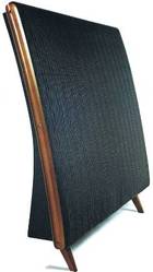
- QUAD ESL 57

By Peter. J. WALKER (Acoustical Manufacturing Co., Ltd.)
Wireless World, May 1955
1. Principles of Design for Operation at Low as well as High Frequencies with Negligible Distortion
A closer examination of underlying principles leads to the conclusion that the electrostatic loudspeaker may well supersede the moving coil for high-quality sound reproduction. Designs recently developed have proved to be capable of reproducing the full audio-frequency range, with harmonic distortions no higher than those of the associated amplifier.
Every loudspeaker designer must, at some time or other, have looked longingly at the electrostatic principal of drive as a solution to his problems of improving quality of reproduction.
The movement of a diaphragm driven all over its surface is entirely predictable. The diaphragm can be as light as required. The impedances influencing performance can be predominantly acoustic and - since there are no shape restrictions - entirely under the control of the designer.
What has held it back?
.
- (1) First, the fact that in its generally known form it is intrinsically nonlinear and even in a push-pull construction linearity can only be approached for small amplitudes.
- (2) Secondly, in order to obtain adequate sensitivity the available gap is small; the diaphragm movement limited and largely stiffness controlled, both factors restricting its use to high frequencies.
- (3) Thirdly, that being essentially a capacitive electrical load, it is difficult to match to an amplifier.
The first of these objections, that of non-linearity, can be removed completely by an expedient which is spectacular in its effectiveness and simplicity.
The second and third difficulties will resolve themselves, as we shall see later, when the designer makes his choice of the interdependent mechanical, acoustical and electrical variables.
.
Fig. 1 (a) shows diagrammatically the connection of a conventional electrostatic loudspeaker in which the polarizing voltage is applied to the centre diaphragm and the signal in push-pull to the outer perforated fixed plates.
.
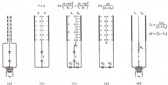
- Fig. I. Essential differences in the operation of electrostatic loudspeakers with "constant voltage " and "constant charge" the centre diaphragm.

Under conditions of no signal, Fig. 1 (b), and assuming the diaphragm to be central, there will be equal and opposite attractive forces on the diaphragm. If one fixed plate is now made positive and the other negative so that the diaphragm will be deflected to the right, the effective capacitance will increase, and to satisfy the relationship "Q=CE" the charge "Q" will also increase and will be supplied by a current "i" during the movement.
The force acting on the diaphragm per unit area will, however, be proportional to :

.
Die Beziehung ist "nichtlinear"
The relationship will be non-linear. Note that the charge "Q", although varying, does not enter directly into the relation.
Suppose that after having charged the diaphragm electrode the source of polarizing potential is disconnected (Fig. 1(d)). The diaphragm now carries a constant charge "Q" which experiences a force proportional to the product of the field intensity and the charge.
This force will be independent of the position of the diaphragm between the plates since both Q and the distance between plates are constants; the only variable is the applied voltage "e". Note that the difference between "dx" and "d2", although varying, does not enter into the relation.
.
Und sie ist vielleicht zu einfach
The above is perhaps an over-simplification, but it shows that distortion is not necessarily inherent in the electrostatic principle.
The "constant Q" method of operation has another very important advantage in that it reduces the risk of collapse, which occurs at large amplitudes with the conventional method of connection, when the negative stiffness resulting from electrical attraction exceeds the positive mechanical stiffness of the diaphragm.
As the diaphragm approaches one of the fixed plates the capacitance is increased, but as the charge "Q" has been assumed constant, "E" must fall since "E = Q/C".
Professor F. V. Hunt und die Wellenlänge
Professor F. V. Hunt(†) of Harvard University has shown, that the criterion for dynamic stability under large excursions is that the time constant "RoCo" of the charging circuit (Fig. 1(e)) should be large compared with l/2f, the half-period of the applied frequency.
This also supplies the condition for low distortion and Professor Hunt gives the results of measurements (Fig. 6.14, p. 212, loc. cit.) showing the dependence of second harmonic distortion on both the degree of unbalance due to displacement of the central electrode (in terms of Deta C/C) and of the ratio of time constant to half period "2fRoCo".
Even when this latter parameter was reduced to unity, and the diaphragm displaced by a distance equivalent to a capacity unbalance of 25%, the second harmonic did not exceed 0.5%, when driven at 150 c/s by 780V r.m.s. (plate-to-plate) with a polarizing voltage of 500. Third and higher harmonics were always less than the second.
So much for the driving mechanism; it now remains to see how it fares when coupled to the air and to an amplifier.
" Electroacoustics " by F. V. Hunt, chapter 6. Published by John Wiley & Sons (Chapman & Hall).
Beginnen wir mit einer großen Membrane
It will help in understanding the broad principles involved if we start by considering a loudspeaker whose diaphragm is large compared with the longest wavelength of sound to be reproduced.
Under these conditions the mass reactance of the air load on both sides of the diaphragm can be neglected and the impedance per unit area "2pc" offered to the motion of the diaphragm is predominantly resistive (pc=42 mechanical ohms per cm2).
With constant voltage driving the diaphragm the force will be proportional to the applied signal voltage and independent of frequency.
If the load is resistive the velocity, and also the acoustic power output, will be independent of frequency.
Besonderheiten bei hohen Frequenzen
At very high frequencies the mass reactance of the diaphragm can exceed the radiation resistance and will cause "a falling off" in velocity when the force remains constant; the acoustic output will then decline by 6db/octave, but, with suitable choice of diaphragm material, not until a frequency of 20 to 25 kc/s is reached.
(How different from the average moving coil in which the cut-off starts at about 1,000 c/s and must be sustained by focusing of high frequencies along the axis or by juggling with cone " break-up.")
und bei tiefen Frequenzen
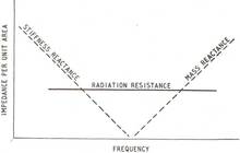
- Fig. 2. Variation of acoustical and mechanical impedances with frequency in a diaphragm which is large compared with wavelength.

Similarly at low frequencies a 6db/octave falling off with reducing frequency will result when the reactance due to the stiffness (reciprocal of compliance) of the diaphragm exceeds the resistance air load.
This state of affairs is shown graphically in Fig. 2. Unfortunately, it is not so easy to put the frequency at which the stiffness begins to exercise control outside the audible range.
Über die Steifheit des Materials
The choice of stiffness will be dictated by the necessity of constraining the diaphragm against the forces associated with the polarizing voltage.
Under "static" conditions (2fRoCo less than unity) these forces can increase as the diaphragm approaches the fixed plates and must be limited by a suitable choice of stiffness, polarizing voltage and plate spacing.
The plate spacing also determines the electrical capacitance of the loudspeaker, and the impedance offered to the amplifier at the frequency chosen for " matching."
Thus the bandwidth available for constant output, under the acoustic conditions postulated, is limited at low frequencies by the diaphragm stiffness required for stability and at high frequencies by the conditions of matching to the amplifier. (The inertia cut-off will always be well above the matching frequency and can be ignored.)
Über den Wirkungsgrad von Elektrostaten
The true efficiency of an electrostatic loudspeaker is very high indeed, but it is difficult to realize because of the large wattless current which has to be provided due to the electrical capacity of the loudspeaker unit.
Thus it is necessary to waste watts in the amplifier or in resistances associated with crossover networks of which the loudspeaker may be part.
For purposes of simplification, therefore, it is convenient to use the term "apparent efficiency" the meaning of which is the ratio of the acoustic power output of the loudspeaker to the amplifier volt-ampere output necessary to provide the required voltage across the loudspeaker capacity.
Beispiele und Illustrationen zur Effizienz
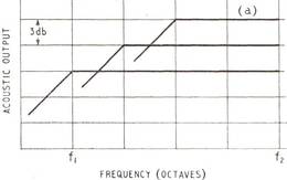
- Fig. 3. Low-frequency response can be extended, at the expense of "apparent efficiency" by increasing the plate spacing and re-matching to the amplifier at f2, the upper frequency limit.

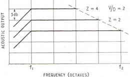
- Fig. 4. Alternatively, with constant spacing and a fixed low-frequency limit the high-frequency response can be extended, again at the expense of "apparent efficiency" by varying the frequency f2 at which the capacitive impedance is matched to the amplifier.

The way in which the designer can trade bandwidth for "apparent efficiency" is illustrated by Figs. 3 and 4. In both cases we assume the maximum output will be available at the high-frequency matching limit, and that constant voltage will be available at this and lower frequencies.
In Fig. 3 let curve (a) represent the response with a given electrode spacing D=l. If we double the spacing the diaphragm stiffness required for stability can be halved and the low-frequency cut-off goes down an octave.
At D=2 the capacitance is halved and the impedance doubled, but because the power is limited the volts rise by only (Wurzel ??) 2 when the amplifier is re-matched.
Thus the field strength V/D available to drive the diaphragm is reduced to (Wurzel ??)2/2 and the response falls by 3db. We have thus gained an octave for a drop of 3db in output, and, of course, the necessity of finding twice the polarizing voltage.
We can, if required, regain the lost efficiency by re-matching an octave lower at the top end, as shown in Fig. 4. We now keep D (and C) fixed, and with it the low-frequency cut-off. The field strength available for driving the diaphragm will be proportional only to the voltage available from the amplifier.
If we re-match an octave lower "Z" will be doubled and "V" will increase to (Wurzel ??) 2, so there will be a 3db rise in acoustic power for the loss of an octave at the high-frequency end.
Über Hifi-Qualität und Effizienz
Since very high efficiencies are not a pre-requisite of high-quality reproduction, it is convenient to arrange the apparent efficiency to be similar to the efficiency obtained from present-day commercial moving-coil speakers.
Setting the efficiency at this level and applying polarizing voltages permissible in the given air gap, we find that the available bandwidth for level response is about four to five octaves.
Below the low-frequency cut-off we have the stiffness of the diaphragm controlling response, a large proportion of it under conditions where the "apparent efficiency" is high and wasted. (At low frequencies the impedance is high, and less power is required to maintain constant voltage.)
Thus, by a progressive change of "matching" in this area, one can compensate to extend the level response below the mechanical cut-off. The effect of this mechanical stiffness is best considered when we deal with possible forms of loading, since it can be lumped in with the acoustical circuit loading the loudspeaker.
A high polarizing voltage is desirable in order to place a high value of charge "Q" on the diaphragm. Each small unit area of the diaphragm can be fed with a high voltage at very high impedance, thus charging up that part of the diaphragm in relation to the fixed plates.
In this arrangement of the loudspeaker, where the signal is applied to the fixed plates only, there are no signal currents due to the wanted signal in the diaphragm itself, so that this arrangement of high-impedance charging of each unit area of the diaphragm is permissible, and is essential for linearity in any practical construction.
Any tendency for the air to conduct between the diaphragm and the fixed plate at any point in the loudspeaker merely causes a slight drop in the voltage at that area of the diaphragm, so that in this way high voltages can be applied without any danger of sparking.
Since the charge on the diaphragm is unvarying, it follows that the force on the diaphragm is completely independent of the position of the diaphragm in the space between these electrodes and the system in linear.
With this arrangement, then, it is no longer necessary to restrict the allowable motion of the diaphragm to a small percentage of the available gap. Again, there is no restriction to the ratio of signal voltage to polarizing voltage.
Die Membrane, das einzige nichtlineare Bauteil der Kette
The only non-linear element entering the system at all is that due to the compliance of the diaphragm, and since in most designs this is not a controlling factor in the motion of the diaphragm its importance is small. There is no difficulty in producing units on this principle, the distortion content of which is even lower than that of present-day amplifiers, and many times better than a moving-coil loudspeaker of normal efficiency.
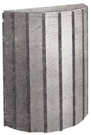
- Fig. 5. High-frequency unit with dimensions large compared with wavelength designed to cover frequencies from 1,000 c/s to the upper limit of audibility.

Schlußfolgerungen :
We have seen, then, that it is now possible to design loudspeakers on the electrostatic principle for a given bandwidth, over which the forces are acting directly on to the air.
We have seen that this bandwidth can be placed anywhere in the audio range and that linearity represents considerable improvement on anything hitherto produced. The design of a loudspeaker unit on such principles is therefore purely one of applying it to its acoustical load to give any required performance.
We have so far assumed the simple case of 2pc loading on the diaphragm. Ignoring for the moment horn loading, this can only be achieved in practice at high frequencies, or for cases where the diaphragm is very large indeed.
Betrachten wir Bild 5
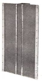
- Fig. 6. Unit of more complex design which, with proper acoustic loading, covers the range from 40 c/s to the upper limit of audibility. Measurements on this and the unit of Fig. 5 indicate total harmonic distortions of less than 1%.

A simple single unit construction for high frequencies is shown in Fig. 5. This loudspeaker covers the range from 1,000 c/s to the upper limits of audibility. Such a unit could, of course, be used with conventional moving-coil speakers for low frequencies, but the assumption that moving-coil units operate like distortion-less pistons at low frequencies is very far from the truth. It is obviously desirable to introduce the benefits of the electrostatic principle throughout the whole frequency range.
By way of showing what can be done, Fig. 6 shows a more complex design of electrostatic loudspeaker which, when properly loaded, covers the whole frequency range from 40 c/s up to the limits of audibility.
Zukünftige Artikel werden zeigen
In a future article it is proposed to discuss the operation of such loudspeakers, i.e., when size is no longer large compared to wavelength, and to show the basis of design approach for the whole frequency range.
Distortion measurements on these units gave figures well below 1%. Measurements were made out of doors, and noise, wind, and other restrictions due to imperfect conditions made it difficult to get reliable figures below 1%. Inspection of the residual waveform indicates that the distortion due to the units is considerably lower than this figure.
Similar remarks apply to frequency response, due to the fact that it is virtually impossible to achieve perfect loading conditions. Measurements produce responses which are within 2db of the predicted curves, but the major part of these small discrepancies may be attributed to the approximations assumed in the structures used for loading.
QUAD baut diese ESL Speaker seit etwa 1953
Since 1953, electrostatic loudspeakers have been the subject of joint development between "Ferranti, Ltd., of Edinburgh", and "The Acoustical Manufacturing Co., Ltd., of Huntingdon". Some of the techniques involved in the design of these loudspeakers are the subject of joint patent applications by P. J. Walker and D. T. N. Williamson.
.
.