Erläuterungen zu diesen 1960er Seiten
Die hier stehenden amerikanischen Artikel aus 1960 (aus der US-AUDIO) sind teilweise sehr gewöhnungsbedürftig, weil sie erstens aus einer längst vergangenen Zeit stammen und zweitens, weil dort in den USA ganz "anders" gedacht wurde als bei uns in Old Germany oder in Europa.
Vergleichbar mit unseren deutschen Hifi-Magazinen etwa ab 1962 ist jedoch, daß auch diese Zeitschrift ihre Anzeigen- Kunden und -Leser (be- oder ab- ?) werben mußte. - Weiterhin sind die Dimensionen des amerikanischen Kontinents mit den unseren hier in Europa nicht vergleichbar. - Ein "Trip" von New York nach Los Angeles oder gar in die Wüste nach Las-Vegas zu einer der Audio- "Shows" war - auch mit dem Flugzeug - immer noch eine Weltreise. Und jede Ausstellung oder "Messe" wurde als "Show" deklariert. Und natürlich, in USA musste alles "Show" sein, um beim Publikum einige Aufmerksamkeit zu erzeugen.
.
Der Titel in der amerikanischen AUDIO Mai 1960 Heft 5
"A 1-7/8-ips Magnetic Recording System for Stereophonic Music"
von P. C. COLDMARK, C. D. MEE, J. D. GOODELL/ W. P. CUCKENBURC
.
Um die Gerüchte zu beenden, eine fundierte Beschreibung :
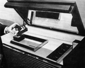
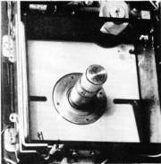
- Prototype of Columbia 1 7/8" tape unit in cabinet.

Rumors about the new tape system have been rampant for several months, but little actual information was available. Here for the first time is a complete description of the tape, cartridges, and handling mechanisms from the best authorities - those who developed it.
.
Columbia und 3M sind schon einige Jahre dabei .......
As part of a long range development program in the field of magnetic recording which CBS Laboratories undertook on behalf of Minnesota Mining and Manufacturing Company, recorded tape systems for the home have been under study over a period of several years.
In order that recorded tape can take an important place in the field of home entertainment, one must take into account a great many requirements, some of which are not easily met.
.
Es sind Voraussetzungen zu erfüllen - zum Beispiel :
.
- 1. The tape must be contained in a compact cartridge in such a way that no part of the tape is exposed.
- 2. The amount of tape must be small and the cost of the cartridge low in order that the price of the final product can approach that of the disc record.
- 3. The sound should be stereophonic with provision for three tracks for maximum flexibility.
- 4. A complete musical composition should be played without interruptions; that is without reversing the cartridge or tape.
- 5. The quality of sound should be at least as good as the best of existing recorded media.
- 6. The durability of the tape and cartridge must be high enough so that after several hundred plays, the sound remains unchanged.
- 7. It should be possible to place a number of cartridges on a tape machine equipped with a changer-type mechanism so that one can provide music for several hours.
.
Was aus diesen Studien herausgekommen ist :
Here we will report on the outcome of these studies and subsequent developments which we believe will satisfy the preceding conditions and requirements.
It was clear from the outset that one was dealing with "a system" rather than just "a few components". Thus intensive development work over a period of several years progressed simultaneously in such areas as methods of signal recording, magnetic transducers and playback heads, design of cartridges and tape transport mechanisms. The Laboratories' system work, in close cooperation with 3M, also included the development of a new tape with characteristics that provided optimum matching into the overall performance.
Late last fall (herbst 1959) the new recorded system was in a sufficiently advanced stage to demonstrate it to many members of this industry.
3M had, at that time, stated that the Zenith Radio Corporation had joined this effort and entered the design of commercial equipment based on these developments.
Hier die wichtigsten Eigenschaften :
Some of the important features and parameters of the new tape cartridge system are as follows:
.
- 1. Tape speed is 1 7/8 ips. The width of the tape is 150 mils; the thickness 1 mil, and there is provision for three tracks. Each track is 40 mils wide.
- 2. The cartridge is approximately 3 1/2" square and 5/16" thick. The cartridge contains sufficient tape to play continuously for 64 minutes, and thus will carry more than 98% of the music compositions available without interruptions. The space occupied by the cartridge in its container is approximately 4 cu.in. as compared with an LP record in its envelope with approximately 20 cu.in.
- 3. The tape machine can take five cartridges and play them automatically one after the other. A cartridge can be rejected during any part of its play similar to a record changer. The production versions of this machine now under development by Zenith will have fast forward and reverse speeds. The same instruments will also serve as a home recorder using the new cartridges with blank tape.
.
The Third Track (für ein Mono-Summensignal)
Earlier reference was made to a third track which is located in the center of the 150-mil tape. Extended studies have been undertaken in the Laboratories to determine the optimum acoustic conditions desired by the listener in the average home while playing recorded music. Conventional stereophonic music, as now recorded, provides only a portion of the sounds that are perceived by the listener sitting in a concert hall.
A large percentage of the total acoustic energy which reaches the listener's ears is reverberated and delayed sound which is considerably depleted of its original stereophonic character.
Experiments in the Laboratories have shown that in a space simulating the average living room, a much more exciting and realistic sound can be produced giving an illusion of "being there". Thus, it is intended to record on the third track as an optional feature on the new recorded tape system, the stereophonic sum signal delayed and reverberated to an optimum degree.
Eine neue Dimension des Klanges sei möglich
The new medium will provide maximum flexibility and a new dimension in sound. The reproducing instruments (die Wiedergabegeräte) can be manufactured for two or for three tracks.
Later some of the electrical and magnetic characteristics of the new system will be discussed. The data and curves shown are already based on the newly developed tape and represent the overall behavior of the entire system, that is, recording, tape, and playback.
The new tape is now in pilot production at 3M, but the cartridges played in current demonstrations still use the older tape on which these programs were recorded last fall (Herbst 1959).
.
Die diversen Probleme und ihre Lösungen
Following the section dealing with the magnetic aspects of the new system, some of the mechanical problems and their solutions as encountered will be described.
A comparison of the new tape system with the original 15-ips tape master from which both the stereo records as well as the new tape cartridges have been derived, has been demonstrated with success. For this purpose, some sections of music were alternately transcribed from the original master and the 1 7/8-ips narrow track version onto a 15-ips halftrack tape.
Magnetic and Electrical Characteristics
In order to achieve an adequate signal-to-noise ratio, frequency response, and dynamic range at a tape speed of 1 7/8 ips, significant developments of most components used in magnetic recording are required. For instance, due to the shorter wavelengths encountered, developments have been aimed at reducing wavelength-dependent losses.
Among the losses in reproduction which have been minimized in the system at hand are those attending
- (1) separation of head and tape surface,
- (2) azimuth alignment of head and tape, and
- (3) playback-head efficiency.
Losses minimized in the recording process are
- (1) tape-thickness loss,
- (2) recording-field configuration loss, and
- (3) loss caused by non uniformity of tape particles.
.
(A) Losses in Reproduction
1. There is an exponential reduction of the playback-head flux with decreasing recorded wavelength due to the finite separation between the surface of the tape and the playback-head pole pieces.
At 15,000 cps and 1 7/8 ips, this loss is almost 0.5db per micro-inch separation.
2. Another important loss is associated with the azimuth alignment between the playback-head gap and the line of constant recorded magnetization across the track width.
For a conventional 90mil track a loss of 6db occurs at 15,000 cps and 1 7/8 ips. for a misalignment angle of 3 minutes.
3. The proportion of playback-head flux shunted by the gap will increase when using the narrow gaps necessary to resolve the shortest wavelengths recorded at a tape speed of 1 7/8 ips. In order to maintain a high efficiency it is necessary to compensate for a reduction in gap length by a corresponding reduction in gap depth.
.
(B) Losses in Recording
1. A separation loss of the type described for reproduction occurs during recording due to the finite coating thickness.
Those particles remote from the tape surface will thereby give an attenuated contribution to the tape-surface flux and so will contribute less to the playback-head flux.
2. The magnetization of a recorded tape will not be uniform throughout the coating thickness since it depends on the rate of extinction and the direction of the recording field when the critical value for recording is reached after the tape has passed the recording gap.
In addition to this, a further loss can occur due to change in phase of the recorded signal through the coating thickness caused by the vertical curvature of the effective recording plane of the recording-head field.
3. For high resolution of the effective recording plane a sharp cutoff of the recording field must be accompanied by a high uniformity in the magnetization characteristics of the individual particles of the tape. Elimination of particles with low critical fields for switching will also reduce self-demagnetization effects. The separation loss has one advantage in slow speed tapes for audio, since, due to the shorter wavelengths involved, print through is correspondingly reduced allowing new thin tape backing materials to be used with safety.
New Developments in Magnetic Recording Components
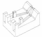
- Fig. 1. Two-track playback head subassembly.

Although the major loss component, called separation loss, is inherent in presently known magnetic recording systems, it has been possible by improvements of tape and heads to achieve performance characteristics approaching those presently obtained from 7.5-ips machines. Such performance is achieved with a track width of 40 mils. Having a narrow track reduces the alignment problem.
It has been found that a conventional laminated ring-type playback head can be constructed to be responsive up to 15,000 cps with a 1.5mv output from a tape having 1/8 mil. coating thickness. A sub-assembly of the two-track version of such a head is shown in Fig. 1.
The playback-head coils fit over the projecting laminations. Since the recorded wavelength at 15,000 cps is only 1/8 mil, it is necessary to form an effective magnetic gap of 1/16 mil (or 1.5 microns.). It has been found that a 1-micron spacer gives satisfactory head resolution in prolonged use.
By manufacturing the multi-track head in two halves, automatic colinearity of the gaps is assured and in practice the 10,000-cps sensitivity of the tracks differ by less than 4db.
Auch der Aufnahmekopf muß geändert werden
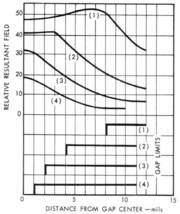
- Fig. 2. Rate of recording-field extinction as a function of gap length.

Similar mechanical refinement is necessary of course in the recording head. Fig. 2 shows a plot of the field distributions at 0.1-mil spacing for various gaps.
It is seen that the field decrement increases somewhat with gaps which are large compared to the spacing. Thus a long gap might be thought advantageous especially since the vertical field decrement is also reduced.
In practice, however, the expected improvement does not occur, probably due to the relatively greater vertical component of the effective recording field. Considerable development has been carried out to improve the recording-field configuration for the very short wavelengths involved in this system. This work will be reported at a later date.
Bedeutende Verbesserungen beim Tape
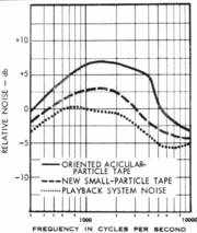
- Fig. 3. Zero modulation noise curves with correct playback equalization plus the 40-phon ear characteristic.

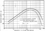
- Fig. 4. Maximum output curves for 1 7/8-ips tape.

Significant advances have been made by 3M in the recording media, leading to considerable reduction of the separation loss effects.
Firstly, a tape "lacquer formulation" (die Mischung der magnetischen Beschichtung) has been developed which is relatively soft, giving good head-to-tape contact. Particle rub-off on guides (das sind die Bandführungen) and heads has virtually been eliminated and the consequent amplitude variations considerably reduced at the shortest wavelengths.
In addition, the Laboratories developed a higher-output and lower-noise tape as a result of changes in the magnetic material itself. Previous work has concluded that a reduction of effective particle size results in lower tape noise.
The improvement achieved is shown in Fig. 3, where the weighted noise response for existing tape is compared with the new tape using optimum bias for each. A 4db lower noise level is obtained in the mid-frequency range. Higher over-all output is also obtained from the new material. It is found that the short-wavelength efficiency is particularly improved. One reason for this is that a deliberate attempt was made to reduce the speed of critical fields required for magnetization change in the individual particles.
.
For acicular particles better control of the size and shape is required and for effectively spherical or cubic particles it is necessary that the acicularity be kept low enough to make the crystal anisotropy dominant in all particles. Figure 4 shows the improvement resulting from recording with the new tape using one of the high-efficiency recording heads compared to that obtained with conventional 1 7/8-ips recording.
.
Equalization Techniques and Performance of the System
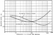
- Fig. 5. Recording and playback equalization curves.

The recording equalization adopted for the new 1 7/8-ips record-replay system is shown in Fig. 5. This curve was derived by performing many listening tests on a variety of program material. It is the characteristic which meets the requirement to load the tape optimally at all frequencies without overload danger.
Using this in conjunction with the playback equalization (also shown in Fig. 5) a flat response is obtained from 30 to 15,000 cps at -18 db relative to a level giving 3% distortion at 1.000 cps.
Under these conditions the ratio of the maximum signal level at 1000 cps to the zero-modulation system noise is 54db. The 10,000-cps signal response at this maximum signal level is -12db relative to that at low frequencies.
Typical equivalent signal-to-noise ratio for professional 7 1/2-ips half-track systems is 54db with a correresponding 10,000-cps signal response at -6db. Thus the new system with its own recording and playback characteristics approaches the 7.5-ips performance available today and has been found to be entirely adequate for all types of musical programs.
Mechanical Design Problems and Solutions
One of the central problems in recorded tape systems is the design of the tape packaging. Obviously, it is necessary to satisfy requirements of convenience as well as to provide adequate protection for the tape. Naturally high-quality performance with respect to music reproduction is a prerequisite.
In order to popularize recorded tape, it is essential to eliminate the process of manual threading between the reels.
This requirement is dictated by the need for avoiding manual threading and also by the requirement to make the cartridge compatible with a practical automatic changer mechanism.
Erste Idee einer Kassette mit 2 Spulen
On first examination the notion (die Idee) of threading the tape permanently between two side-by-side reels contained in the cartridge is attractive. However, every practical design incorporating both the supply and take-up reels in the cartridge requires that sections of the tape be exposed through openings in the cartridge walls with consequent dangers of damage.
Even in a single cartridge player there are many difficulties involved in coupling the tape of a dual-reel cartridge to the drive system and the heads, but when the design of an automated changer is considered, these problems increase rapidly in number and magnitude.
Gefordert war auch schnelles Umspulen
A basic consideration in any type of cartridge is the need for relatively high speed transport in so-called "search" operations. If flanges are used on the reels inside the cartridge, the bulk is considerably increased and many problems of stability are encountered. Thus, high-speed winding without flanges requires some method of maintaining a separation between the tape and the cartridge walls.
The three dimensional geometry of the reeled tape, the driving spindle in the transport mechanism, the walls of the cartridge and other components call for strictly orthogonal relationships or some automatic dynamic adjustment and an accurate system of tape guidance.
Otherwise, the cumulative errors in repetitive reeling of the tape, even on the same machine, will lead to telescoping or angular displacement of the tape reel with respect to the cartridge walls. In brief laboratory experiments these problems may not be evident but in long-term field use the increasing friction produces instabilities in the tape speed and eventually may completely block the reel from rotating.
The problem of smooth reeling without any flanges was solved by introducing a novel guiding member in the cartridge with adequate compliance to insure a smooth rewind cycle.
This arrangement allows a tape with an hour of playing time to be rewound in twenty seconds. (A five-second rewind time has been achieved in the laboratory.)
Das Band ins Gerät "einziehen"
Threading of the tape (das Band einziehen) is accomplished by means of a leader (Zugband) permanently attached to the takeup reel (Aufwickelspule) in the mechanism. The end of the rewind cycle leaves the permanent leader in the threading path of the machine.
A very simple and economic solution was used for the design of the coupling between the reeled tape and the permanent leader.
.
- Anmerkung : Dieses Zugband-System wurde erst 1984 bei der Firma DEC perfektioniert. Vorher hatte es nur mittelmäßig funktioniert. Die Elektronik war 1960 noch lange nicht so weit. Mehr steht bei den DLT Laufwerken im Magnetbandmuseum.
.
Eine Erläuterung des Einzugssystems von 1960

- Fig. 6. Cartridge coupling members.

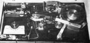
- Fig. 7. Tape deck, showing felt pad.

This consists of a "U" shaped device attached to the end of the tape in the cartridge and so shaped that it seals off the only opening in the cartridge when the tape is fully rewound. The permanent leader terminates in a dumbbell-shaped element that readily mates with the "U" shaped clip. The dumbbell attached to the permanent leader can slip through the "U"-shaped clip in a vertical direction with only a light detenting restraint but provides an absolute coupling in terms of horizontal pull when the two members are engaged. (Fig. 6).
In order to eliminate variations in back tension with dynamic changes in effective reel diameter, a felt pad is spring-loaded against the surface of the tape as it leaves the cartridge and the supply reel is operated in free-running bearings. This provides excellent tensioning characteristics and at the same time maintains the cartridge complexity cost at a minimum. Figure 7 shows the tape deck and the felt pad.
Gebraucht wird auch ein Bremsmechanismus
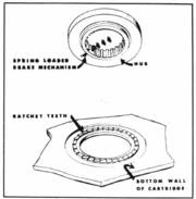
- Fig. 8. Cartridge brake mechanism.

Some kind of braking mechanism is essential in order to avoid partial unreeling and fouling of the tape within the cartridge under normal conditions of handling. The brake must be positive,
reliable, and simple to assemble.
The device selected consists of a linkage mounted in the cartridge hub and spring-loaded in a ratcheting relationship with teeth molded in the cartridge wall. When the cartridge is placed on the machine, the spindle releases the brake automatically. The brake is shown in Fig. 8.
- Anmerkung : Nocheinmal auf das DLT Laufwerk von 1984 verweisend, hatten deren Entwickler nur elektronische Bremen vorgesehen. Der Servomotor war nämlich Antrieb und Bremse zugleich.
.
Über das Rückspulen in die Kassette
- Fig. 9. Close-up of cartridge spindle and well.

The facility for driving the cartridge hub during the rewind cycle must be designed so as to permit random rotary orientations of the spindle with respect to the cartridge hub in the loading process.
This is accomplished by means of radial slots around the inner periphery of the hub and a spring-loaded-two toothed drive in the spindle. See Fig. 9.
The cartridges are designed with mating surfaces that couple them (see Fig. 10) together in a stable vertical stack. This feature contributes considerably to the ease with which they may be handled and loaded in a changer mechanism. The patterns are unsymmetrical so that the cartridges must be correctly oriented or they cannot be fitted together. Other details of the mechanism make it impossible to load the cartridges in any way that results in improper operation.
Das sich ergebende Cartridge Gehäuse .....
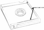
- Fig. 10. Diagram showing cartridge nesting ribs.

The resulting cartridge design is compact, inexpensive and dependable. Actually, of course, the cartridge design was carried on in conjunction with the development of mechanisms capable of handling it in a fully automated changer so as to eliminate any mutually exclusive features.
The actual changing mechanism consists simply of a spring-loaded platform in a well (Fig. 9) with which the supply spindle is coaxial, and an appropriate escapement. The latter is an essentially conventional device.
There are two escapement levers that operate in tandem on opposite sides of the cartridge well. One of the escapement levers is placed close to the corner from which the tape is fed in order to maintain accurate positioning between the clip terminal and the threading path.
The path for the tape is a straight line from the cartridge to the supply reel during the threading operation. When the tape has been pulled from the cartridge and starts to wind on the supply reel, the pressure pad that supplies the back tension and the pressure roller are automatically brought into position. (Fig. 10) - The takeup reel is operated with a conventional slipping clutch drive. The successive cycles of operation are programmed by means of a multiposition rotary switch and several mechanical interlocks.
.
Die Funktionen im Betrieb ....
The slipping clutches, brakes, speed-changing idlers, and the like are operated from the three-dimensional surfaces of a single complex cam which programs all pressure-pad, pressure-roller, and escapement operations.
It is necessary to provide a number of mechanical and a few electrical interlocks to prevent improper manual interference with machine operations, but these are relatively simple and straightforward in design.
.

The straight-line character of the tape path does not require intermediate idlers and consequently the guidance problems are minimized. However, as in all such drives, it is important to maintain the pressure roller axis parallel to the axis of the capstan.
This is accomplished by introducing sufficient compliance in the mounting of the pressure roller so that it is self-adjusting within small limits. The spring loading provides a simple adjustment for correcting major pressure differentials across the idler surface. (Fig. 11).
Die Band-Ende Erkennung
Obviously, there must be some means for sensing the end of the tape and various other portions of the operating cycle. In this machine these results are obtained by means of a simple analog computing linkage that cannot be disclosed in detail at this time. However, the method is independent of the length of the tape in a given cartridge and has displayed a very high degree of reliability.
The authors wish to express their appreciation for the advice and assistance during the course of this work by
B. B. Bauer, A. A. Goldberg, J. C. Jeschke, H. R. Sherman, E. L. Torick, and J. C. Wistrand of CBS Laboratories and Barbara Ivins, formerly with CBS Laboratories. We also wish to acknowledge whole-hearted cooperation of Dr. W. W. Wetzel and his associates of 3M's Magnetic Products Division.
Nachtrag viele Jahre später (März 2019)
Auch dieses CBS Cartridge-System - übrigens wie auch das RCA Cartridge-System 2 Jahre vorher - war viel zu kompliziert und die ganze Band-Steuer-Logik musste mechanisch gelöst werden. Das hatte 1962/1963 der Philips Mann in Belgien, der das erste Philips Diktiert-Gerät mit der CC Kassette entwickelt hatte, viel einfacher hinbekommen.
.