Von 1973 bis 1975 stand das "Quadro-Lager" in Flammen.
- Viele völlig unbekannte japanische Firmen wollten 1972 in den Quadro Markt

Als bei uns in Deutschland die Quadrophonie so um 1971 ihren Anfang nahm, waren die Japaner (seit 1970) schon weiter. In den Labors mußten verkaufsfähige Geräte entwickelt werden und in den (japanischen und amerikanischen) Marketing- Abteilungen wurden die Vorlagen der "Verkaufstexte" so blumig wie nur möglich formuliert.
Daß dabei - eine sehr lange Zeit - die Wahrheit auf der Strecke blieb, war erst mal egal, denn "sie" brauchten alle ein Produkt, das süchtig machen sollte. Es gab aber - leider - weltweit ein paar kritische Geister, die die Physik gnadenlos analysierten und den interessierten Hörern oder Lesern die echten physikalischen Details um die Ohren schlugen. Das kam nicht immer gut an, denn die großen Konzerne hatten - selbstgemachten - Leidensdruck.
Neben dem Deutschen Dr. Karl Günter Schwartz (Doktorarbeit über die Abnutzung von Nadel und Platte) gab es die beiden japanischen Autoren Takeaki Anazawa und Masanori Kimizuka von Nippon Columbia und hier den Japaner Mitsuo Nemoto von Audio Technica.
Alle waren tief in der Entwicklung der notwendigen Hardware drinnen und hatten eigentlich nur die Aufgabe, alle Ecken, Haken und Kanten bestmöglich zu umrunden und ein irgendwie funktionierendes Produkt auf die Beine zu stellen. Und es gab hier bei uns in Deutschland das Military Magazin off-duty des Amerikaners Walter Rios, in dem noch mehr realistische Quadro-"Wahrheiten" standen.
SHURE wußte, warum sie sich zurückgehalten hatten ......
Erst im Jahr 2020 bin ich über die 1974er CES Berichte eines Amerikaners gestolpert, in denen er immer wieder bemerkt oder kritisch betrachtet hatte, warum die US-Firma SHURE keine CD-4 Abtaster auf den kleinen und großen Messen vorstellen wollte (oder konnte ?), selbst in 1974 nicht.
Die Antwort an den neugierigen amerikanischen Redakteur aus Old Germany - Walter Rios - war lange Zeit, "wir arbeiten dran". Und SHURE war der Weltmarktführer bei Abtastsystemen und das SHURE V15 III und IV (und folgende) waren weltweit die unbestrittene Referenzklasse, sogar bei großen Stückzahlen.
Dieser Artikel wurde im März 1973 fotokopiert.
Wie können nicht mehr herausfinden, in welcher Zeitung oder welchem A3 großen Magazin der Artikel abgedruckt war. Alle Anzeigen (in englisch) sind ausschließlich mit Kontakt-Adressen in Japan versehen.
Auf den sehr flauen Kopien steht nirgendwo der Titel drauf. Ich mußte die Fotokopien erheblich und mit großem erheblichen Aufwand nachbearbeiten. Die Bilder sind zwar gräuselich aber dafür aussagekräftig.
Das Resumé des Artikels steht ganz unten.
.
- Report-Logo Seite 30
FEBRUARY 1973 - Four Channel Repport
"Technical Features, Possible Problems"
1. Preface
The basic problem in playing recorded music is how music can be reproduced which approximates the original sound field. This problem has been the basis for development of the four-channel concept.
The constant search for more realistic reproduction of sounds on records has been the prime force behind the progress from the 78 rpm to the 33-1/3 rpm monaural LP to the stereo LP (rpm = Umdreh. / min).
Now that stereo has advanced from the two-channel to the four-channel system, the prerequisite for improvement is considered higher sound quality, greater density of information, and reduction of loss.
The matrix four-channel and discrete four-channel systems have each resulted in intensive examination of reproduction problems and the result has been improved performance. In this article, problems encountered in pickup cartridges designed for four-channel use will be examined in an effort to put them in perspective as they relate to the two reproduction systems.
Problems confronting cartridges in the matrix four-channel system and in the discrete four-channel system will be treated separately.
2. Problems of Pickup Cartridges For Matrix Four-Channel Systems
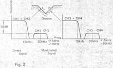
- Bild 2

Problems in this system are typified by the orientation and separation of sound images produced from the four speakers. In the matrix system, the directivity and atmosphere of sound are controlled by changes in the phase.
Consequently, reverse phase components inevitably enter the matrix source, causing a deterioration in the orientation of the sound image. Resolving this problem during recording is impossible, so it must be taken into account during, reproduction.
- Anmerkung : Auf dem obigen Diagramm zur Aufteilung der benutzen Frequenzbänder bei CD-4 sieht man immer wieder die Presse-Bilder von RCA / JVC, bei denen die Frequenzband-Aufteilung nicht korrekt abgebildet wird. Denn die immer genannten 30 kHz ±15 kHz (also bis 45 kHz) sind ganz dicht an der Grenze zum Grundspektrum von 20 Hz bis 15 kHz. Über den Verbleib der originalen auf dem Masterband befindlichen Hifi-Musikinformationen oberhalb von 15 kHz bis 20 kHz schweigt man sich aus. Die sind nämlich auf CD-4 Platten einfach nicht drauf. Der Hardware-Entwickler Louis Dorren hat das in seinen Recherchen gnadenlos offengelegt.
.
One method is a phase shift
One method is a phase shift of 90° or 45°. The phase shifter can easily achieve accuracy of 90° ±5° in the 100 Hz to 10 kHz band. Following is an outline of the normal procedure for matrix four-channel reproduction. Output from the pickup cartridge is rendered into four-channels by means of the matrix circuit with front and rear crosstalk (constants of A = 0.18, 0.35, 0.414, etc.) determined in advance.
Then phase shifting of each channel is executed and the result amplified to obtain the real output. Another procedure is addition of reverse phase components, corresponding to crosstalk components and their levels, to the phase-shifted output. This is done to improve separation as well as the sense of orientation of the sound. The important task of the pickup cartridge here is to transduce the mechanical signal, i.e., the phase, recorded on the disc accurately and transmit it to the matrix circuit.
If the phase should be changed broadly at the time of transducing operation, separation may not take place and sound that should be produced may be erased or distortion may develop.
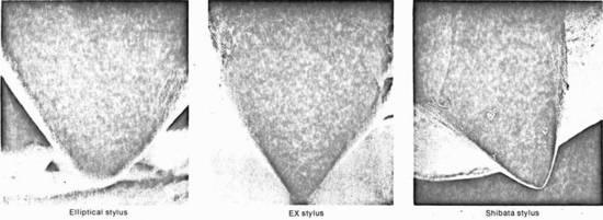
- Hier ein Vergleich der wichtigsten Nadelschliffe aus den Labors von Audio Technica

Über die Vermeidung von Abtatsverzerrungen
The following factors prevent distortion by the pickup cartridge at the time of phase shift.
- 1) The needle should not have enough resonance to cause a phase shift of more than 11° within the matrix four-channel reproduction band. With a high-grade pickup cartridge, resonance arising from the equivalent mass of the playing needle and the equivalent stiffness of the record normally exists between 12 kHz and 20 kHz. With popular cartridges like the ceramic types, resonance arises between 6 kHz and 10 kHz. For this reason, either the mass of the vibrating system should be reduced to a minimum or adequate damping should be applied to suppress the phase shift that accompanies resonance. Phase shift with a high-quality cartridge is about 15° at maximum, but with the popular type, it is about 30° at maximum.
- 2) The output balance between the left and right channels should be uniform and stable within the band.
- 3) Tracking of the playing needle should be true and amplitude mixing and modulation distortion should be low. If distortion is high, particularly in the vertical direction, the rear channelwill suffer from distortion and poor orientation.
- 4) The pickup should have a minimal lateral tracking error rate. It is desirable that the axial line of the vibration be identical with the junction line of the sound groove, since phase shift is related to the magnitude of the error.
.
Hier die Bewertung ...
As the above factors are not peculiar to matrix four-channel reproduction, many pickup cartridges on the market satisfy them completely. Since these problems have been dealt with successfully in two-channel reproduction, there should be no trouble in four-channel reproduction. Some caution is advisable, however, as some OEM cartridges may exhibit the phase shift characteristics described above.
.
3. Problems Attending Discrete Four-Channel Cartridges
Problems attending discrete four-channel reproduction are typified by the possible mixing of noise from a variety of causes into the difference signal band, i.e., into the sound reproduced through the rear speakers.
However, such problems have already been identified and solved at disc recording, disc pressing and reproduction stages.

3.1 CD-4 Discrete Recording
As shown in Fig. 1, the four sound sources of the CD-4 disc are converted into the sum signal (Chl+Ch2; Ch3+Ch4) and the difference signal (Ch1—Ch2; Ch3—Ch4).
In order to improve SN, the difference signal passes through the compressor and FM-PM-FM equalizer and undergoes angular modulation to get 30 kHz as the carrier. The modulated signal and the sum signal mentioned before become the left signal of Ch1+Ch2 + (Ch1-Ch2) and right signal of Ch3+Ch4 + (Ch3-Ch4) at the next mixing circuit.
These then pass through the cutting equalizer containing reverse RIAA characteristic to undergo cutting. As with a normal stereo record, the left signal mentioned before is cut on the left-hand wall of the sound groove at a 45-degree incline, while the right signal is cut on the right-hand wall of the sound groove.
The frequency at this point, as shown in Fig. 2, is distributed over a wide band. Turntable speed at the time of cutting is reduced to 1/2,7 of 33-1/3 rpm. (also eta 1/3 der 33 1/3 Umdrehungen)
In the following, the current state of the four-channel cartridge, which made compatible 2-chan-nel and CD-4 reproduction possible, and its various characteristics will be discussed.
3.2 Needle Pressure (und die "mechanical impedance")
In two-channel stereo reproduction, problems have been caused by the relation of tracking to distortion and the relation of needle pressure to abrasion of the sound groove.
These are particularly important in the CD-4 disc. The difference signal band has higher mechanical impedance with the CD-4 disc, as shown in Fig. 2.
Standard level (OVU) used is 22.3 mm/sec and the modulated signal is amplitude recorded at constant speed at a low level of 20 dB, facilitating reproduction needle tracking on the disc side.
Mehr über die mechanische Impedanz lesen Sie hier.
.
Nicht mal 13% der Abtaster können 45kHz abtasten
However, a survey of the market has shown that there are no more than 13% two-channel reproduction magnetic cartridges with mechanical impedance sufficient to execute tracking up to 45 kHz.
At the contact point between the sound groove wall and the tip of the stylus, the sound groove wall is subjected to concentrated pressure. The sound groove wall undergoes either flexible or plastic deformation.
Consequently, if the needle pressure is too high, high range attenuation and sound groove abrasion take place; if the needle pressure is too low, tracking of the sound groove becomes poor and results in distortion.
.
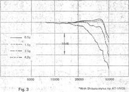
- Bild 3

Needle pressure of two grams should be considered the maximum. Fig. 3 shows the amplitude loss arising from flexible deformation of the sound groove of a record and the high-range attfenuation resulting from increased mechanical resistance, in this case using a CBS STR-120 stereo record.
In existing two-channel stereo, reproduction sound could be obtained even at high needle pressure. However, as the pickup cartridge for CD-4 has an output voltage of more than 1 mV at 30 kHz and as the difference signal circuit works normally even under higher needle pressure, the sound is frequently distorted by noise.
.
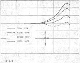
3.3 Load Resistance and Stray Capacity
- Bild 4

The demodulator input impedance is 100kOhm and 30pF. The target stray capacity is held to 100pF from the pickup cartridge tip to the input terminal capacity mentioned above. Normally this total capacity is distributed between 70 pF and 350 pF and is dependent upon the lead wire of the player.
This necessitates correction with a low-capacity lead wire. In case an inductive magnetic cartridge is used, frequency response attenuation takes place in the difference signal band. Because of the drop in the 30 kHz output, a problem will develop in the difference signal circuit.
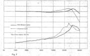
Fig. 4 shows the load impedance against frequency response in a well-known moving magnet type magnetic cartridge. A marked change in the treble range is evident because of the load.
- Anmerkung : Hier sieht man die von den Laboroingenieuren nachgemessenen Frequenzgänge, wenn die Impedanzen der Abtastsysteme variieren bzw. nicht stimmen.
.
3.4 Temperature Characteristics
Any disc using polyvinyl chloride and vinyl acetate polymer as the main materials is subject to change in the frequency response under the influence of temperature fluctuations.
The response, in other words, changes in proportion to the frequency and to the temperature. The resonance frequency arising from stiffness of the disc and the mass of the vibrating system is particularly subject to the influence of temperature.
The needle support bearing, which both supports the needle and provides the damping effect, is made of a rubber-material. Since it is damping the resonance mentioned before, its changes are marked.
A normal magnetic cartridge undergoes, at 30 kHz, a 4 to 5 dB change between 5°C and 20°C. As this impedes operation of the difference signal circuit, caution is necessary.
3.5 Output Voltage
As the cartridge output is unaffected in the sum signal band of the CD-4 disc, minimum 0.5 mV or above (speed amplitude of 3.54 cm/sec. at 1 kHz) is appropriate. The normal magnetic pickup cartridge poses no problem as an output of 2 to 5 mV is obtained.
However, there is correlation between the high-range reproduction frequency range of the vibrating system and the output voltage. In case the output voltage is high and efficiency is good, the high-range reproduction frequency range is liable to be narrow in many cases.
As the difference signal circuit operation uses 30 kHz as carrier, the output voltage of the difference signal band at 30 kHz may well be 1 mV or higher (speed amplitude of 3.54 cm/sec at 30 kHz). It must be noted, however, that this value takes into account losses resulting from the effect of temperature, needle pressure and load impedance.
3.6 Crosstalk
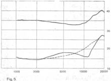
- Bild 5

The left and right channel separation of both the sum and difference signals is dependent on their relation to the conventional 45°/45° operation, as can be seen from the frequency distribution shown in Fig. 2, making desirable as wide a separation as possible between 20 Hz and 45 kHz.
This same separation has been the requirement for the two-channel pickup cartridge. The conventional two-channel cartridge achieves separation of at least 25 to 30 dB at 1 kHz and 15 to 20 dB at 10 kHz. These are sufficient for the sum signal band.
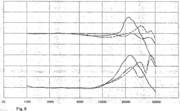
While the requirement for the difference signal band is 15 dB or above, attention should be paid to crosstalk response. Fig. 5 shows crosstalk response of two types of moving magnet magnetic pickup cartridges. The crosstalk shown by solid lines against the dotted lines appears good, as a marked dip is evident around 8 kHz to 18 kHz.
However, the relationship between the disc and the stylus point is normal when the frequency lower than 18 kHz (in the stiffness control area centered on the treble resonance frequency) rises in a slow curve of 6 dB/oct.
The dip, therefore, means phase rotation, and the apparently excellent crosstalk is an error; the dotted line shows far more stable and excellent crosstalk response. This also applies to the difference signal band. In the band given an angular modulation and having 30 kHz as carrier, and in the area with high signal density, a particularly stable crosstalk response of 15 dB or higher is required.
3.7 Frequency Response
As shown in the frequency distribution (Fig. 2), a flat response between 20 Hz and 15 kHz is good enough for the sum signal, and the response as it is results in sound quality. For the difference signal, flat response between 20 kHz and 45 kHz is required as an ideal.
.
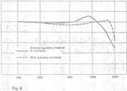
- Bild 6

- Bild 7

- Bild 8

However, the resonance frequency arising from the effective stiffness of the record and the effective mass of the vibrating system on the stylus tip is distributed between 15 kHz and 22 kHz in the so-called high-quality two-channel cartridges.
At frequencies higher than 22 kHz, rapid level attenuation takes place. In many of the CD-4 cartridges now available, resonance arising from factors mentioned above is set at around 30 kHz.
For frequencies higher than 30 kHz, a flat response is obtained through damping, applied by putting the compound resonance into the vibrating system. In Fig. 6 responses stemming from the presence or absence of the compound resonance are shown.
Also, as typified by the Shibata stylus, it is possible to extend the resonance to a higher sound range. This is done by dividing the mass of the vibrating system through an increase in the effective contact area of the stylus tip touching the sound groove wall.
In Fig. 7 the frequency response of a Shibata stylus and that of an elliptical stylus are shown, with the same curvature radius taken for the side contact.
3.8 Playing Needle
- Bild 9

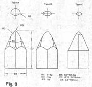
Some types of styli used for CD-4 pickup cartridges are shown in Fig. 9.
Basically, the curvature (radius) of the side contact of the stylus tip which comes into contact with the sound groove wall is 5 to 6 uR.
Also, to reduce signal level loss and abrasion, R grinding as big as 75uR is given.
Larger or smaller differences in form arise from differences in the grinding process, but the operating effect of the sound groove and the stylus tip may be considered equal.
.
- Type A is the Shibata stylus. This consists of a combination of two-face cutting and conventional conical stylus tip grinding.
- Type B is the extension stylus and Pathe-Marconi stylus. In this type, 75 uR and side contact curvature are uniformly provided for the 75 uR part of conventional elliptical styli.
- Type C is the Ichikawa stylus tip. Processing similar to that of Type B is done to the tip of a quadrangular pyramid.
.
- Bild 10

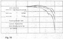
In any case, larger curvature of the side contact part of the playing stylus, together with effects mentioned above, results in high-range frequency response losses through differences in the diameter of discs at inner and peripheral parts.
This has even posed problems for the conventional two-channel system, and since losses arising from differences in the diameter of records become larger in the difference signal band, such playing styli are needed. Fig. 10 shows the effect produced by a Shibata stylus.
3.9 Frequency Modulation Distortion And Playing Stylus Pivot
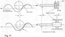
- Bild 11

More than 3000G acceleration is applied to the playing stylus. For this reason, the stylus supporting unit must be provided with a mechanism capable of resisting such an acceleration. If the supporting mechanism is poor, carrier modulation develops in the difference signal band while the stylus tip generates frequency modulation.
This not only results in development of beat frequency but also gives rise to frequency mixing and modulation distortion. Fig. 11 shows the action of a stylus fixed with a piano wire, stretched to resist the sound groove tracing direction, and that of a stylus supported only with visco-elastic rubber.
With the latter, delay in, delta t is corrected by an escape of vibration, which arises from quick acceleration and large mass, toward the composite direction of the sound groove tracking direction vector and vibration direction vector.
(This article has been contributed by Mitsuo Nemoto, Audio Technica Corp.)
.
Resumé im Dezember 2020 zu den CD-4 Adaptern:
Als bei uns so um 1971/72 diese "QUADRO" Euphorie aufkam, wußte nach spätestens 1 Jahr niemand mehr, wohin der Weg wirklich geht. Auch bei BRAUN, SABA, DUAL, Isophon und GRUNDIG usw. war es so.
Also mußten externe Adapter bzw. die externen CD-4 Demodulatoren her. Und nun fingen die Probleme an. Die Japaner von JVC hatten zwar die Theorie in den Specs definiert und publiziert, aber das Wissen um die notwendige Hardware sollten sich "die Deutschen" (Hersteller waren gemeint) mal schön selbst aneignen.
Bei den ganz ganz wichtigen großen Plattenfirmen hier bei uns und in ganz Europa stieß dieses Denken sowieso schon auf Widerstand und bei den Hardware- Firmen auf nur mäßiges Verständnis.
Die allermeisten Phono- Stereo- Vorstufen wurden von 40 bis 18 kHz beschnitten bzw. mehr oder weniger steilflankig "abgesägt". Unter 40 Hz gab es sowieso nur Brummen und Rumpeln - in einem normalen Wohnzimmer sind 40 Hz Töne sowies physikalisch gar nicht hörbar - wegen der Wellenlänge - und oberhalb von 18 kHz war da dieser böse laute 19kHz Stereo Pilotton, der einstreuen "konnte" - jedenfalls vielleicht.
Also wurde in den externen CD-4 Adapter (DUAL, Grundig, Marantz usw.) ein eigener oft höherwertiger RIAA Entzerrer eingebaut und das Plattenspieler- NF-Kabel wurde mit Schalt-Kontakten dorthin umgeleitet bzw. "durchgeschleift".
Laut Prospekt natürlich völlig problemlos und absolut optimal, weil dann bei einer technischen Weiterentwicklung nur dieses Teil ersetzt (nicht getauscht sondern neu gekauft !!!) werden mußte. Das klang alles toll, war aber leider ein technologischer Flop.
.
Aber wie immer, das war nur die halbe Wahrheit ...
Im REVOX B251 Verstärker (und natürlich auch bei anderen hochwertigen Teilen) fällt auf, daß man sogar an der Frontseite die Eingangsimpedanz des Abtasters mitsamt dem Kabel umschalten konnte (oder anpassen sollte). Die Studer Ingenieure wußten nämlich genau, welche Effekte eine (kapazitive) Unter- oder Überanpassung von Abtaster und Eingangsstufe nach sich ziehen.
Sowohl DUAL als auch Thorens und Revox haben immer wieder darauf hingewiesen, daß das originale mitgelieferte und angelötete Phono-Anschlußkabel bitte NICHT durch angebliche High-End Kabel ersetzt werden solle. Es sei oder ist ein genau optimiertes Teil der Gesamtimpedanz des Abtasters - also der Verdrahtung bis in den Tonarm !!.
Aber Highender sind sowieso viel schlauer als diese dummen Ingenieure da in den dunklen Labors. Also da müssen neue Stecker dran, natürlich teuer und hochglanz-vergoldet und neue Leitungen müssen auch her.
Es gab und gibt da hahnebüchne Konstrukte und esoterische Empfehlungen in bestimmten Foren, die einem die Haare zu Berge stehen lassen.
.