Das englische Manual des CROWN DC300A
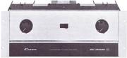
- das waren die ersten DC300A

- damals imposante technik

Das Manual an sich wird nur Wenige interessieren, die solch eine Endstufe noch besitzen oder betreiben. Interessanter ist, was die Amerikaner alles in das Manual rein geschrieben hatten und vor allem - die Schaltpläne. Diese Endstufe war zur damaligen Zeit um 1972 etwas ganz Besonderes. Solch einen Watz in dieser Form gab es nirgendwo. Entweder gab es die mechanisch wackeligen Home-Hifi Geräte der ganz wenigen deutschen Hersteller oder die "hübschen" Verstärker von den Japanern oder die wenigen professionellen Endstufen der extrem wenigen Studio-Profis wie Klein+Hummel und Telefunken und Sennheiser.
Doch keiner dieser Hersteller konnte Lasten im 2 Ohm Bereich verkraften, die allermeisten schalteten bereits bei 4 Ohm und Voll-Last ab. Und von satten 600 Watt Sinus an 8 Ohm (20-20.000Hz in der Mono-Brückenschaltung) träumten die Europäer nicht mal, denn "sowas" braucht "Mann" ja sowieso nicht - wurde uns traumatisch wiederholend erklärt. Entweder wußten sie es nicht besser (traurig) oder sie konnten es nicht besser (noch trauriger). Das mit den großen Diskotheken und sonstigen Bühnen-Beschallungen und der geforderten Leistung waren eben besondere Anforderungen und hohe Maßstäbe.
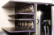
Das gesamt Gehäuse als Kühlfläche, toll.
Natürlich vergleiche ich diesen DC300A Verstärker von 1973 mit den damaligen Endstufen von Harman Kardon oder Marantz oder The Fisher oder McIntosh oder dem damals auch ganz neuen BOSE 1800 Endverstärker. Doch bis auf den BOSE 1800 waren das alles Hifi-Endstufen, und schon gar nicht für die Diskos geeignet. Alleine der BOSE 1800 von 1974 konnte mit diesen allen konkurrieren und setzte bei seinem Erscheinen neue Maßstäbe. Doch darauf antwortete CROWN mit dem M600. Und die ganzen 40 und 60 Watt Bastler- Endstufen von Radio RIM und Dynacord waren so weit außerhalb jeder Diskussion, darüber braucht man heute kein Wort mehr zu verlieren.
.
INSTRUCTION MANUAL TABLE OF CONTENTS


Section 1 DESCRIPTION
1.1 General
1.2 Specifications
1.3 Warranty
Section 2 INSTALLATION
2.1 Unpacking
2.2 Mounting
2.3 Normal Hi-Fi Installation
2.4 Connecting Output Lines
2.5 Connecting Input Lines
2.6 Connecting Power
Section 3 OPERATING INSTRUCTIONS
3.1 Controls and Adjustments
3.2 The Protection Mechanisms
3.3 Operating Precautions
3.4 Load Protection Methods
3.5 Cleaning (Unsinn)
Section 4
4.1 Principles of Operation
4.2 Test Procedures
4.3 Service
Section 5 APPLICATION NOTES
LIST OF ILLUSTRATIONS
1 -1 DC-300A Pictorial
1 -2 DC-300A Performance Graphs
2-1 Mounting Dimensions
2-2 Normal Hi-Fi Hook-up
2-3 Rear View of Chassis
2-4 Source Resistance and Damping Factor vs. Length and Size of Output Leads
2-5 Schematic For Full Range Electrostatic Speaker Connections
2-6 Schematic of Earphone Pad
2-7 Table For Selection of Input DC Blocking Capacitor
2-8 Low-Pass Filter For Severe RF At Inputs
2-9 Table of Line Voltage Connections
3-1 Operating Controls
3-2 Graph of VI Operating Range of DC-300A Output
3-3 Fuse Selector Nomograph For Loudspeaker Protection
3-4 Relay Controlled Protector with Overload Indicator
3-5 Peak Power Limiting Compressor with Overdrive Indicator
3-6 Turn-On-Transient "Muter" (kommt von "muting" = leise schalten) For Load Protection
1.1 GENERAL
The DC-300A is a dual-channel high-power amplifier for precision amplification of frequencies from DC to 20KHz. The unit features extremely low harmonic- and intermodulation distortion, very low noise, highest "damping factor," and quality parts and workmanship. Because of the large output power, it is possible to obtain a monaural 70-volt balanced line without using an output transformer.
The DC-300A contains a new CROWN developed Signal Programmed Automatic Current Executor (SPACE control) electronic amplifier protection circuit which manifests no flyback pulses, thumps, or shut-down.
At audio frequencies any impedance load including totally reactive loads may be driven with no adverse (negativen) effects. Only maximum output power will be affected by variations in load impedance. At sub-sonic to DC frequencies the limiter acts as a VI (Spannuns-Strom) limiter to provide optimum protection for the extremely rugged silicon hometaxial output devices (total of 16 for a total of 2.400W dissipation).
A pair of thermal switches remove power from the unit if overheating occurs due to insufficient ventilation. The AC line is fused to protect the power supply.
See Section 3.2 for a description of the protective systems.
Technical Features
The power supply features a 1 KW transformer and large computer-grade filter capacitors giving over 48 joules of energy storage.
A total of 37 discrete transistors, 1 linear IC (dual opamp), 24 diodes, 1 bridge rectifier, and 3 zener diodes are used in the DC-300A circuitry. With the integrated circuit, the effective number of semiconductors is 53 transistors, 34 diodes, and 3 zener diodes.
The output devices, 8 per channel, are conservatively employed, having a total peak current rating/channel of 120 amps in a circuit that is limited to a maximum of 28 amps. Among its unique features, the circuitry includes the CROWN-pioneered and patented AB+B output configuration.
The input operational amplifiers are powered by two voltage-regulated supplies. This results in complete channel-to-channel isolation and independence from line voltage variations.
Total direct coupling results in perfect, instantaneous, thump-free overload recovery even on non-symmetrical waveforms. This cannot be said for any AC-coupled amplifier presently in existence. Turn-on is instantaneous with no thumps or program delays.
Front-panel controls include two independent heavy-duty level controls and a power switch with an associated pilot light. DC balance controls, which never need adjustment in normal operation, are located behind the front-panel.
1.2 SPECIFICATIONS
.
- Frequency Response
±0.1db DC - 20KHz at 1 watt into 8 ohms, ±1db Zero-100KHz (see graphs). - Phase Response
+0, -15° Zero-20KHz, 1 watt into 8 ohms (see graphs). - Power Response
+1db, -0db DC -20KHz at 150 watts RMS into 8 ohms (see graphs). - Power at Clip Point Typically
190 watts RMS into 8 ohms, 340 watts RMS into 4 ohms per channel (see graphs). - Total Output (IHF) Typically
420 watts RMS into 8 ohms, 800 watts RMS into 4 ohms (see graphs). - I.M. Distortion (60-7KHz 4:1)
Less than 0.05% from 0.01 watt to 150 watts RMS into 8 ohms, typically below 0.02%.
Less than 0.01% at 150 watts (see graphs). - Damping Factor
Greater than 200 Zero to 1KHz into 8 ohms (see graph). - Hum and Noise(20-20KHz)
110db below 150 watts RMS output (unweighted, typical 122db). - Slewing Rate
8 volts per micro-second (S-R is the maximum value of the first derivative of the output signal). - Load Impedance
Primarily used at 4 ohms or greater; maximum power at 2.5 ohms, lower impedance affects only maximum power; will drive a completely reactive load with no adverse effects. - Input Sensitivity
1.75 volt +2% for 150 watts into 8 ohms (see graphs). - Input Impedance
Nominal 100K ohms, 10K ohms at full gain (see graphs). - Output Impedance See graphs, next pages.
- Turn-On Instantaneous, with no thumps or program delay.
- Output Protection Short, mismatch, and open-circuit proof; protection operates with no flyback pulses, thumps, or shutdown.
- Overall Protection
Line voltage is independently fused. Thermal switches in AC line protect against overheating caused by insufficient ventilation. Controlled-slewing-rate voltage amplifiers protect overall amplifier against RF burnouts. Input overload protection is furnished by internal resistance at inputs of amp.
.
Power Supply 1KW transformer with heavily-heat-sinked high-current diodes and massive computer-grade filter capacitors storing over 48 joules of energy. Two regulated supplies for complete isolation and stability.
Power Requirements Requires 50 to 400Hz AC with adjustable taps for 120, 128, 240, 248, and 256V +10% operation. Draws 40 watts or less on idle, 500 watts at 300 watts output into 8 ohms per channel.
Heat Sinking Massive black-anodized heat sinks are thermally joined with chassis, thereby utilizing the entire amplifier as a heat sink. Chassis All-aluminum construction for maximum heat conduction and minimum weight. Heavy aluminum front panel is a single extrusion.
Controls Heavy-duty independent input level controls are on front panel. Power switch, with adjacent pilot light is on front panel. Non-interacting DC balance controls are mounted behind front-panel.
Connectors
Input - 1/4 inch phone jack.
Output - Color coded binding posts.
AC Line-Three-wire (grounded) male connector on 5 ft. min. cable.
Dimensions 19" standard rack mount, 7" height, 9 3/4" deep (from mounting surface).
Weight 45 pounds net weight.
1.3 WARRANTY
CROWN guarantees this equipment to perform as specified. CROWN also warrants the components and workmanship of this equipment to be free from defects for a period of 90 days from date of purchase.
This warranty does not extend to fuses, and/or component or equipment damage due to negligence, misuse, shipping damage or accident; or if the serial number has been defaced, altered or removed.
An application for a FREE 3-year WARRANTY TITLE is included with this manual. Upon receipt of this completed form, CROWN will issue the Warranty Title - subject to the conditions contained therein. This title applies to the original end-purchaser and will be issued only upon the receipt of the application.
We urge that you take full advantage of this coverage - fill in and mail the application now!
Section 2 - INSTALLATION
2.1 UNPACKING
As soon as the amplifier shipment is received, please inspect for any damage incurred in transit. Since the unit was carefully inspected and tested at the factory, it left the factory unmarred. If damage is found, notify the transportation company immediately. Only the consignee may institute a claim with the carrier for damage during shipment. However, CROWN will cooperate fully in such an event. Be sure to save the carton as evidence of damage for the shipper's inspection.
Even if the unit arrived in perfect condition - as most do - it is advantageous to save the packing materials. They will prove valuable in preventing damage should there ever be occasion to transport or ship the unit. Note the carton and internal pack - each is designed for protection during transit, particularly of the power transformer weighing over 25 lbs. Do not ship the unit without this factory pack!
Be sure to return the warranty registration form to the factory within ten days for the full warranty coverage.
2.2 MOUNTING
The DC-300A is designed on a standard 19 inch rack-mounting format. However, it may be custom mounted if sufficient support is provided. For dimensions see Fig. 2-1. In any circumstance, sufficient ventilation must be provided for the unit. Good ventilation practice allows air to flow completely under, around, and through the amplifier. If the unit is placed above a horizontal surface, an air space should be allowed above and below the unit. If sufficient ventilation is not provided, the unit will intermittently turn off due to the built-in thermal protection. Such a condition (if observed) will also be accompanied by a warm front-panel due to the integral heat-sinking employed in the amplifier.
Applications requiring long sustained signals at high power levels may require the use of a cooling fan.
2.3 NORMAL HI-FI INSTALLATION
1. Remove output covers, exposing dual binding-posts. Two-conductor speaker cables must connect to the OUTPUTS using terminal lugs, tinned ends, or the special "banana" plugs supplied with the DC-300A. Connect the in-line fuses as recommended in the Accessory Bag and Fig. 2-2 Overleaf. (Not needed with CROWN speakers.)
2. Since the DC-300A is a "basic amplifier," the main outputs of the control-center or "preamplifier" must be connected via shielded audio-cables to the two jacks marked INPUT. Use RCA-pin at preamp and standard 1/4" phone-plug at the DC-300A.
The two cables should be tied parallel along their entire length, using the accessory cable ties.
3. U/L requirements specify a 3-wire AC power connector; however, proper connections to a switched outlet on the control center require the use of a 3-to-2 wire adapter. NOW, plug the AC into a switched outlet on the control center.
4. Your Control Center may now be turned on. Then advance the DC-300A Input-Gain Controls about 1/2-open (150° clockwise).
When using the CROWN IC-150 Control-Center, the LOUDNESS should attain almost full rotation (2 to 4 o'clock) for loudest "concert-hall" volume.
If at 3 o'clock the volume is low, increase the DC-300A input gain controls; if too high, decrease the DC-300A gains.
To assure maximum enjoyment and full speaker protection, read the following detailed sections on OUTPUTS, INPUTS and Chapter 3 -OPERATION.
2.4 CONNECTING OUTPUT LINES
Input and output connectors are located on the back of the chassis as shown In Fig. 2-3.
It is always wise to remove power from the unit and turn the input level controls off while making connections, especially if the load is a loudspeaker system. This will eliminate any chance of loud blasts. CROWN is not liable for damage incurred to any transducer due to its being overpowered! (CROWN speakers excepted.)
Before making connections, it is recommended that the operator familiarize himself with the amplifier's protective system. See Section 3.2. Section 3.3 entitled "Operating Precautions" should also be read.
Because of the location of the output connectors (color-coded binding posts), it will be easiest to make these connections first. High-quality, dual "banana" plugs are the preferred connections for permanent installations, critical applications, and when testing the amplifier.
Because the output wire gauge and length raises the resultant source impedance or lowers the Damping Factor by adding its series resistance, the nomograph (Fig. 2-4) is provided for wire selection.
Diffeence dynamic moving-coil and electrostatic speakers
For dynamic moving-coil loudspeakers the value of RL (Impedance) should preferably be that measured by an ohmmeter across the voice coil, rather than the manufacturer's rating. For electrostatic speakers and such, the manufacturer's rated impedance should be used for R.
If the load (matching transformer, inductance, or full-range electrostatic speaker system) appears as a short-circuit at low frequencies, a large non-polarized capacitor (paralleled with a resistor) should be placed in series with the load.
For electrostatic speakers (if the manufacturer has not provided a capacitor) an external non-polar capacitor of 590-708 mfd and 4 ohm power resistor should be placed in series with the plus (+) speaker lead. This will prevent large low-frequency currents from damaging the electrostatic transformer or from unnecessarily activating the DC-300A's protective systems. An effective test to determine if such parts are needed is to measure the DC resistance between the output terminals with an ohmmeter. If the resistance is less than 3 ohms, the parts should be added as shown schematically in Fig. 2-5.
general precautions
When selecting connectors for the output lines, the following general precautions apply (with all power connectors):
1. A male plug, carrying signal, must not be on the far end of the line where it can be exposed, giving rise to both shock and short-circuit hazards.
2. Connectors which might accidentally cause the two channels to be tied together during making and breaking of connection should not be used. A common example is the standard 3-circuit Va inch phone jack and plug when wired for stereo sound.
3. Connectors which can be plugged into AC power receptacles should never be used.
4. Connectors having low-current-carrying capacity are "verboten."
5. Connectors having any tendency to short, or having shorted leads, are unadvisable.
Most commercially-available headphones employ a 3-circuit 1/4" phone plug which violates condition number 2. This is no handicap if a pad is inserted between the amp and jack, which is the only sensible thing to do, when such a large amplifier is coupled to such a small transducer. If this precaution is ignored, not only may the transducer be burned out but permanent hearing loss could result. The recommended pad is shown in Fig. 2-6.
2.5 CONNECTING INPUT LINES
Connecting the inputs will require avoiding three basic dangers: Undesirable signals to the inputs, "ground loops," and feedback from output(s) to input(s).
For loudspeaker-driving applications, the input should be free of any DC, as this could cause overheating of the loudspeaker voice coil. A simple visual test for DC on the inputs (providing the woofer is visible) is to slowly turn up the input level control with the amp on and watch for any displacement of the cone. If very much displacement is observed, the DC content of the input may be excessive and require a blocking capacitor.
The graph of Fig. 2-7 indicates the effect of the size of the blocking capacitor on the frequency response. Only a low-leakage type paper, mylar, or tantalum capacitor should be used for this purpose.
Taking care for some problems
If large amounts of ultrasonic or RF frequencies are found on the input, such as bias from tape recorders, etc., a low-pass filter should be placed on the input. While practically- obtainable RF input levels will not damage the amplifier, they may cause burn-out of tweeters or other sensitive loads, activate the amplifier's protective systems, or cause general overload in the controlled-slewing-rate stage of the amp (which is employed to provide RF overload protection). The following filters are recommended for such applications.
A second problem area is "ground loops" - electronic jargon for undesirable circulating currents flowing in a grounding system. A common form of loop (possibly resulting in hum in the output) is a pair of input cables whose area is subjected to a magnetic hum field, (n practice, both cables should lie together along their length, and away from the power transformer. Tying the input and output grounds together may also form a ground loop.
A third problem (with input and output grounds together, as in testing or metering) is feedback oscillation, from load current flowing in the loop. In industrial use, even the AC power line may provide this feedback path. Proper grounding, and isolation of inputs of common AC line
devices is good practice. Refer to Section 4.2, par. 5 for testing precautions.
An extremely common form of this problem is encountered when using electrostatic loudspeakers or any other kind of load that is joined to the AC power mains. Capacitive coupling through the load's supplies may allow the amplifier's output to be fed through the AC mains and into the grounds of input equipment resulting in a system oscillation.
How to solve some problems
To combat the problem, first try reversing the speaker leads on all channels if possible. If this does not solve the problem, try grounding the power amplifier to the AC ground with its 3 wire plug. (A ground loop may result through an FM tuner with an earth-grounded antenna system when deploying the 3 wire plug. The use of .005uF disc capacitors in series with the FM antenna leads will eliminate this problem.)
All hookup (interconnecting) cables should of course be as short as reasonably possible, and a turntable baseplate ground should always be brought to the phono preamp with a separate ground wire, never via the input cable ground. If the oscillation still persists, start removing input devices, working towards the amplifier until the oscillation disappears. This will identify the point of feedback. If an offending piece of equipment is found it should be inspected for unnecessary AC line-to-ground capacitances such as line filters, etc. If possible such should be removed. Such devices should never be found in the load, although it is true that some RF loudspeakers have used such filters to reduce RFI.
2.6 CONNECTING POWER
The amplifier is furnished with a three-wire AC plug as standard equipment. Adapters are readily available commercially for adapting this to a two-wire system if necessary.
The amplifier offers five standard line-voltage connections: 120, 128, 240, 248, and 256VAC. The tag attached to the line cord indicates for which voltage the amplifier is connected. Most units inthe US are connected for 120VAC. If the amplifier is used on lines which at any time exceed 130VAC, the unit must be reconnected for 128VAC.
When testing the amplifier, the line voltage must be the peak equivalent to a sinusoid of the indicated line voltage when at full load. Line regulation problems can introduce serious errors in the measurements on an amplifier of this size.
Only a competent technician should attempt alteration of the line voltage connections.
In order to change the voltage, it is first necessary to carefully detach the bottom cover from the unit. On the back of the board-mount subchassis a terminal strip with solder-on jumpers is used to make the line-to-transformer primaries connections (see Fig. 2-9).
Section 3 - OPERATING INSTRUCTIONS
3.1 CONTROLS AND ADJUSTMENTS
The DC-300A contains all the facilities essential for a high performance amplifier.
On the front panel are located independent level controls, a power switch, and pilot light. There is an AC line fuse on the rear of the unit.
The level control should be adjusted for the desired amplifier gain or output level. When the control is fully CW, the gain is 26db as determined by precision 1% resistors in the DC-300A's feedback loop.
The DC balance controls located behind the front panel seldom, if ever, need adjustment. Only in the most critical applications will they need adjustment (not "hi-fi" or similar applications).
To adjust the DC balance controls, use the following procedures (see Circuit Board layout in Section 4):
1. Make sure amp has been allowed at least 15 minutes of warm-up.
2. Set corresponding level control fully CCW.
3. Remove input signal from corresponding input.
4. Place sensitive DC voltmeter across output.
5. Adjust output balance control using small flat-bladed screwdriver for zero reading on voltmeter.
6. Turn level control CW to 12 o'clock.
7. Adjust input balance control using small flat-bladed screwdriver for zero reading on voltmeter.
The DC balance controls are now adjusted.
3.2 THE PROTECTION MECHANISMS
The DC-300A is protected against all the common hazards which plague highpower amplifiers, including shorted, open, and mismatched loads; overloaded power supplies; excessive temperature; chain destruction phenomena; input overload damage; and high frequency overload blowups.
Protection against shorted and low impedance loads is provided by the Signal Programmed Automatic Current Executor (SPACE control). It functions as an automatic current limiter at audio frequencies whose value of current limiting threshold is dependent on the history of the output signal. Output current causes the threshold to decrease while output voltage causes the threshold to increase. The no signal threshold is high enough to allow tone bursting, (even into 4 Ohms) without premature limiting as is found in some recent products of other manufacturers.
Since the limiter has no instantaneous response to output voltage, flyback transients do not appear in the output when limiting occurs on inductive loads. Flyback transients are a necessary response of a VI limiter (sometimes misnomered an "Energy Limiter") when limiting drive to an inductive load. The actual response of the flyback pulse is that the amplifier yields to the load resulting in a pulse emanating from the load which returns the inductive energy of the load to the opposite polarity power supply of the amplifier as that supply that produced the excessive output. The audible effect of flyback pulses is to produce a rasping, popping sort of sound which is not pleasing.
The fuse inherently protects the power supplies against overload. The AC line for 120, 128VAC is fused with a 10A 250V type AB fuse (on 240, 248VAC, 5A type 3AG 250V).
The use of any other size fuse will invalidate the warranty.
Never change fuses with power applied!
Thermal protection
On each heat sink (see Fig. 2-2) is mounted a thermal switch which protects the amplifier against insufficient ventilation. If either heat sink becomes too hot, the AC line power will be interrupted until the temperature falls to a safe level, whereupon power will be automatically restored. When such an event occurs, the external symptoms are: no indication of AC power (by the pilot), and a warm front panel.
All of the amplifier's voltage-amplifier circuitry is designed to be inherently current-limited. Thereby, if any of the devices should fail, (which is extremely unlikely), no damage will occur to the rest of the stages.
The input stage is protected against overdrive damage by a series limiting resistor should the input signal level ever become very excessive.
The amplifier features a controlled slewing-rate which, coupled with the SPACE controller, protects the amplifier from blowups when fed large RF input signals.
3.3 OPERATING PRECAUTIONS
The following are a number of operating precautions given as an aid to understanding proper and improper amplifier usage:
.
- 1. Use care in making connections, selecting signal sources, and controlling the output level. The loudspeaker you save may be your own. CROWN is not liable for any damage done to loads due to careless amplifier usage or deliberate overpowering ( excepted). For pointers on load protection see Section 3.4.
- 2. Never parallel the two outputs by directly tying them together or parallel them with any other amp's output. Such connection does not result in increased power output. Damage incurred by such operation is not covered by the warranty.
- 3. Never drive a transformer-coupled device or any other device which appears as a low frequency short (less than 3 ohm) without a series isolating capacitor. Such operation may damage the device and/or needlessly waste output power.
- 4. Do not short the ground lead of an output cable to the input signal ground as oscillations may result from forming such a ground loop.
- 5. Never remove fuses with power applied.
- 6. Operate and fuse the amplifier only as set forth in Section 3.2.
- 7. Operate the amplifier from AC mains of not more than 10% above the selected line voltage and only on 50, 60, or 400Hz AC. Failing to comply with these limits will also invalidate the warranty.
- 8. Never connect the output to a power supply output, battery, or power main. Damage incurred by such a hookup is not covered by the warranty.
- 9. Do not expose the amplifier to corrosive chemicals such as soft drinks, lye, salt water, etc.
- 10. The amplifier is not recommended for high power industrial usage at frequencies above 20KHz.
- 11. Tampering in the circuit by unqualified personnel or the making of unauthorized circuit modifications invalidates the warranty
- 12. Do not expose the output leads to areas likely to be struck by lightning. Such an installation could invalidate the amplifier.
.
3.4 LOAD PROTECTION METHODS
The most common of all load protection schemes is a fuse in series with the load. The fuse may be single, fusing the overall system. Or, in the case of a multi-way speaker system, it may be multiple with one fuse on each speaker.
Fuses help to prevent damage due to prolonged overload, but provide essentially no protection against damage that may be done by large transients and such. To minimize this problem, high-speed instrument fuses such as Littlefuse 361000 series are most appropriate for such applications. For a nomograph showing fuse size vs. loudspeaker ratings refer to Fig. 3-3.
overdrive solutions
Another form of load protector is shown schematically in Fig. 3-4. Whenever the load is overdriven, a relay switches a lamp in series with the load, smoothly relieving the overload. The lamp then doubles as an overdrive indicator as it glows. If overdrive is unreasonably severe, the lamp will serve as a fuse. By adjusting the relay tension adjustment and the protection level control, this system is useful from 25 to 200 watts for a typical 8 ohm load.
Another more sophisticated form of overload protector relieves the overload by controlling the amplifier's input signal which is creating the overload. This form of protector not only saves the load but also eliminates amplifier overload. With this device, it is possible to operate the amplifier at its maximum level with a minimum of clipping.
This device is shown schematically in Fig. 3-5. It features an overdrive indicator, distortionless photo-optical control, and a Protection Level control giving adjustment from 1W to 200W when driving 8 ohms.
A common problem which causes damage and irritation is the turn-on thump problem typical to many signal sources. Fig. 3-6 shows the schematic of a muter (Abschwächer oder sogar Abschalter) which, when inserted in the input signal line, mutes for several seconds before connecting the source to the amplifier, thereby eliminating turn-on transients. It also removes turn-off transients occurring after the relay drops open (=0.1 sec).
Section 4 - CIRCUITRY
4.1 PRINCIPLES OF OPERATION
The DC-300A has two totally direct-coupled amplifier circuits which employ a dual IC opamp and silicon transistors in all stages. The CROWN designed and developed circuit represents a level of quality and performance presently unequaled in the field of audio amplifier design.
As is implicit in the term "totally direct-coupled," the DC-300A has a perfectly flat frequency and phase response extending to OHz or DC. Flat to DC response results in not only low frequency amplification with absolutely no phase-distortion, but also in perfect overload characteristics.
Non-symmetrical waveforms (such as music) cause overload thumping in all currently produced AC amplifiers. These same amplifiers may, however, show no signs of thumping when fed a symmetrical test waveform such as a sinusoid. DC frequency response combined with ultra-low noise and IM distortion results in the closest approach to a "straight wire with gain."
Input stage with dual op amp
The dual IC op amp is of a low noise type having a large gain bandwidth. The result of using it for the input voltage amplifier is that a maximum amount of feedback is applied reducing distortion to record low values.
The typical full output (150W, 8ohms) SMPTE IM is 0.002%. This implies that the full power THD is in the vicinity of 0.0005%. This has been confirmed by measurement with an elaborate test setup employing CROWN-developed state variable filters and wave analyzing equipment. No other presently available harmonic distortion test apparatus is capable of such low residuals. The 300A's low distortion is achieved by employing multiple feedback loops to allow a maximum of total feedback.
The lack of noise is evidenced by a typical 20Hz - 20KHz effective input noise of 1.25 u volts which produces an effective 8 ohm output of 80 micro-micro (pica) watts.
the output stage
The output stage is a quasi-complementary format employing the CROWN class AB+B technique which uses no bias current in the output transistors. The result is maximum efficiency with minimum crossover notch distortion and amplifier idling-heat. Thus there is no bias current adjustment, as the output circuit is not temperature-tolerance critical. Temperature drifts of bias are further controlled by bias servos which are mounted on the heat sinks.
In the AB+B output circuit, the driver transistors carry the bias current, while the output transistors serve only as boosters. The output transistors (1.200W dissipation per Ch) sense when the driver transistors are delivering significant current to the load and take over and deliver the large load currents.
Protection against shorted and low impedance loads is provided by the CROWN-developed SPACE (Signal Programmed Automatic Current Executor) control circuit. It functions as an automatic current limiter at audio frequencies and as a VI limiter at subaudio frequencies. The threshold of current limiting is dependent on the history of the signal, yet the no-signal threshold of current limiting is high enough to allow full power tone bursting. The net result is total protection with a maximum of headache-free output power requiring neither an inventory of special fuses or cumbersome load matching techniques.
Almost no DC drift and no adjustment
The monolithic input amplifier stages result in extremely low DC drift. The input terminal bias current is offset by a unique temperature compensated source resulting in a laboratory amplifier needing no user-accessible offset controls.
The input amplifiers are powered by zener-regulated power supplies. The bias regulators are also powered by zener-regulated current sources with the result that line voltage variations do not cause noise or distortion due to misbiasing.
The power supply is a continuous-duty type, capable of 1KW loading. The power transformer, weighing 25 pounds, is constructed of special grain-oriented steel. The main DC supplies are full-wave capacitor input type with heavy-duty, chassis heat-sinked diodes. Computer grade electrolytics furnish over 48 joules of energy storage. A higher voltage at low current is derived from a half-wave voltage-doubler circuit. This voltage is used in the amplifier's driver circuit.
The DC-300A represents nothing short of the highest quality in both circuitry and components. It should provide a lifetime of trouble-free service for the most discriminating users.
4.2 TEST PROCEDURES
The sole function of this section is to list precautions essential to obtaining accurate measurements when dealing with high-power, high-purity amplifiers such as the DC-300A.
.
- 1. Use the proper line voltage, which is the one for which the amplifier is connected. The voltage should be measured throughout the testing with a peak reading meter, and adjusted to the RMS equivalent voltage (to compensate for line voltage regulation errors during the course of the measurements). All measurements should be taken at the power amplifier's plug.
- When testing for IHF music-power measurements, the line voltage is to be set at 120V when the amplifier is connected to 120V, (IHF standards). If the amp is connected otherwise, the equivalent test may be given by applying 128 volts on 128V, 240V on 240V, or 256V on 256V line.
- 2. The load should be resistive, having less than 10% reactive component at any frequency up to five times the highest test frequency. The resistor should be capable of continuously dissipating the full output of the amplifier while maintaining its resistance within 1% of its rated value. The load should employ only high-current connectors (if any), and be connected to the binding-post output terminals. All output measurements should be taken at the amplifier output terminals, and not anywhere along the output cable through which the load current is flowing.
- 3. The input level controls should be set to maximum for all distortion tests to assure repeatability of all measurements.
- 4. When measuring hum and noise, all inputs should be disconnected from the amplifier and the level controls set to minimum or to maximum, preferably minimum.
- 5. Whenever possible avoid ground loops in the test equipment caused by connecting the output ground to the input ground. Never connect the ground of the cable going to the load back to the input ground.
- Ground loops are especially obnoxious when measuring distortion. An IM distortion analyzer, for example, has its input and output terminals tied to a common ground. Such a test should use an ungrounded output return, with the output lead(s) wrapped around the well-shielded and grounded input cable.
- 6. Always monitor the test oscillator when measuring frequency response. Use a wide-band AC voltmeter; or use the same meter for both input and output level measurements, if the meter's frequency response is known not to be dependent on attenuator settings.
- 7. Accuracy in measuring voltages for computing wattage is critical. For example, a 2% voltage error together with a 1% resistance error can result in an error of 10 watts power into 8 Ohms.
- 8. Residual distortion and noise levels should be fully known for all the test equipment in order to accurately evaluate the amplifier.
- 9. Never attempt to measure damping factor by placing abnormal loads on the output. D-F measurements taken during clipping, or any other form of overload, axe meaningless. The preferred method is to apply an externally generated current to the output terminals and measure the resultant voltage at the terminals. A convenient current is one ampere - as the resultant voltage will read directly in ohms for |Zo|. Damping Factor is defined as Zl / Zo, where |Zl| is typically 8 ohms. A convenient generator for the 1A. current is that amplifier channel not under test. A non-inductive resistance of 8 ohms - coupled between both channels' output terminals - will provide 1A when 8 volts are impressed across the resistor (by that channel not under test).
- 10. Never measure hum and noise when in the presence of strong magnetic fields. The amplifier should be at least 4 inches away from any large metallic objects or shield plates for a reading to be meaningful.
- 11. Noise measurements should be taken with a bandpass filter of 20-20KHz. For audio purposes the measurement of noise above 20KHz is meaningless.
.
4.3 SERVICE
Should service other than routine fuse replacement ever be required, it is recommended that the unit be returned to the factory in the original packing (or replacement, if damaged). For warranty service the machine must be returned to the factory or warranty service station. The CROWN warranty is detailed on page 11.
Because of the level of circuitry sophistication of the DC-300A, only the most competent technicians should be allowed to service it. Many of the parts are standard items stocked by most supply houses. However, there are several which appear to be standard parts but are actually different. Although standard parts may be used in an emergency, best results will be with factory parts. A number of the parts are available only from CROWN.
When ordering parts, be sure to give the amplifier serial number as well as the part number and description. Rated firms will be billed, otherwise shipments will be C.O.D. (=Barzahlung).
Before returning an amplifier to the factory for service, authorization should first be obtained from the service manager. All shipments must be sent by Railway Express or truck freight, prepaid and insured at total value. The factory will return your serviced unit by Railway Express or truck freight, collect, and will add C.O.D. charges (=Barzahlung) in the event that the cost is not covered by registered warranty.
.
Section 5 - APPLICATION NOTES
Evaluating the VI (volt-ampere) needs of a load: Many loads exhibit large reactances (or energy storage), which limits a power amplifier's ability to deliver a maximum power. If a load stores energy, which in turn flows back into the amplifier, it is clear that the maximum power efficiency of the system is not being achieved. Power that flows back into a linear amplifier must necessarily be dissipated in the form of heat. A pure reactance is not capable of dissipating any power; therefore to drive such a load would only cause power amplifier heating.
In practice all loads exhibit some energy dissipation - however large their energy storage characteristics may be. The ideal coupling to any load is one that optimizes the desired dissipation component while minimizing the reactive or stored-energy component that is seen by the amplifier's output terminals.
In applications where the input is sinusoidal and of small proportional frequency deviation, a relatively stable load may be resonantly tuned to present a real value of impedance to the amplifier.
Any load, no matter how complex its behavior, has a V-l operating range which may be mapped by the following test.
The maximum voltage and amperage excursions in all directions about zero (center of scope screen) define the volt-ampere operating range of the load. If a load is known to be linear over its operating range it is not necessary to supply the maximum desired power to the load. The test may be conducted at low signal levels and the current-sensing resistor (indicated as 0.1 ^u) may be enlarged to a convenient value for the oscilloscope's deflection sensitivity. The resulting plot may be then linearly scaled to the desired operating level.
DC-300A MONO CONVERSION
APPLICATION NOTE NO. 2
How to do :
.
- A. Access to circuit board
- 1. Remove screws (4 top and 4 bottom) mounting top and bottom covers to front panel.
- 2. Remove mounting screws (2 each end) connecting front panel to heat sinks.
- 3. If front panel will move more freely, proceed to step 4. If front panel is stilly contacting the heat sinks at both ends, loosen screws in top and bottom covers to free front panel.
- 4. Carefully lift the front panel straight out from between the heat sinks, being careful not to tilt the panel in any direction until it is free of the amp, and also being careful not to scratch the interior surface of the rack mounting bars with the front panel ends.
- 5. Set the panel down carefully to avoid scratching it or straining the level control cables by which it remains attached to the amplifier.
- B. Wiring changes
- 1. On the exposed circuit board, locate printed circuit sockets A, B, C, and D (Fig. 1), being careful to distinguish them from other sockets on the board.
- 2. Mount a 2W length of insulated hookup wire (W of insulation stripped from each end) by inserting the ends into sockets A and B. (This operation grounds the channel 2 input.)
- 3. Mount a 10K , 1% tolerance, Vi watt resistor with insulated leads by inserting the lead ends into sockets C and D. (This feeds the channel 1 output signal into the channel 2 inverting input.)
- C. Reassembly: reverse the procedure of step A.
- D. Operation
- 1. Make output cable as shown in Fig. 2.
- 2. Connect one lead to HOT (red) amplifier output post of channel 1, the other lead to HOT outpu* post of channel 2.
- 3. Connect any desired load to the output cable A fuse is recommended! (CROWN speakers excepted.) (Refer to Fig. 2-2 on page 13 of the DC-300A manual.)
- 4. Connect input signal, using standard Va" phone plug, to the channel 1 input jack. The channel 1 level control will adjust the gain. (The channel 2 input and level control are bypassed and inoperative in this mode.)
- 5. The 3-wire AC power cord meets U/L requirements. Many installations will require a 3-to-2 wire adapter to avoid ground loops, or multiple ground paths which may allow circulating ground currents.
.
Performance Specifications - Mono bridging
.