Das CD-4 Quadro System von 1973

Das konkurrierende CD-4 Quadro-System von JVC basierte auf der echten hochkomplizierten 4-Kanal Codierung mit 4 diskreten Kanälen. Eine JVC-Broschüre aus März 1973 gibt darüber Auskunft.
Natürlich werden (wie immer) nur die Vorteile herausgestellt, vor allem gegenüber dem Pseudo-Quadro-SQ Verfahren, die (meiner Meinung nach erheblichen) grundsätzlichen Nachteile werden gepflegt verschwiegen.
Darum ein Blick auf die Nachteile: Unser Rundfunk war selbst über UKW nicht in der Lage, diese unkomprimierte diskrete "Quadro Bandbreite" auch nur irgendwie zur Verfügung zu stellen, noch war die ganz und gar ungeeignete 33er Schallplatte dazu in der Lage.
Über die recht schnelle Abnutzung der 33er Vinyl- Langspielplatte bei Frequenzen von über 8 KHz steht hier wesentlich mehr, als Viele bisher wußten. Und CD-4 wollte (mit der speziellen Shibata Nadel) dann sogar die Frequenzen bis 35 Kilohertz problemlos abtasten. Doch das war nicht korrekt bzw. seriös dargestellt.
.
CD-4 INTRODUCTION - Eine Einführung (auf Englisch)
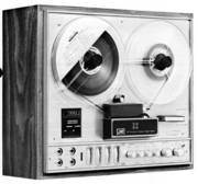
- ein allererstes 4 Kanal Bandgerät


- Der Director, K. Suzuki

Message from Mr. K. Suzuki, the Director in charge of JVC's Stereo Division.
This booklet has been specially written to give people concerned with sound an understanding of JVC's CD-4 discrete 4-channel system. It is addressed to dealers in and salesmen of both hardware and software and all audio writers and critics who, in the course of their work, will have to deal with the CD-4 system.
Audio realism is the watchword behind JVC's progress. Ever since JVC emerged as a company in its own right there has been a continuous quest for perfection. The aim has been to give the consumer the wherewithal to recreate in his living room exactly the conditions that existed where the recording was made.
As you may or may not know the 45/45 stereo system was independently developed in Japan by JVC. This was merely a step in the direction of reaching "audio realism". CD-4, compatible discrete 4-channel, is yet another step. I do not claim that it is the ultimate step, but I think I am justified in claiming that it is the most important step to have been taken in audio for many years and will establish the recording standard for many years to come.

This booklet does not set out to be a full technical description of the CD-4 system but it will give people concerned with audio a good understanding of the principles involved.
Why 4-Channel ?


From Edison to the 1950s played back sound was monaural. The quality of the sound improved over the years but the sound remained monaural. A sound field which originates from one source cannot sound like anything other than it is. And when you're in a live listening environment the sound doesn't appear to come from just one place.
The late 1950s brought 2-channel stereo. This was a big advance over mono; with the sound coming from two speakers instead of one the apparent source could be anywhere between the two speakers. You could actually hear the singer move and the violinists were on the left and the brass was on the right just like in the live performance.
But even though 2-channel was a big improvement over mono, something was still missing. At a live performance there's a 3-dimensional sound field; it's made up from sound coming from the orchestra (or rock group) and reflections from the walls, ceiling and floor. It's this that gives the sound its unique quality. But two speakers cannot create a 3-dimensional sound field; to do this accurately you must have four speakers, each producing its own sound.
The need for 4-channel sound was admitted by audio experts several years ago but technical obstacles stood in the way of implementing it. Reel-to-reel tape decks were the first source to be used to produce 4-channel sound. With these tape decks the obstacles were not so great and four fully discrete channels could easily be recorded to and picked up from 1/4" wide magnetic tape. The next program source that was used for discrete 4-channel playback was 8-track cartridge tape. Here again the problems were not so great. But tape decks are not such a popular program source. Reel-to-reel decks only have a 5% market penetration, and this is confined to real hi-fi enthusiasts.
To make 4-channel really marketable, what was needed, was a disc system. So audio engineers throughout the world set about seeking a 4-channel recording and playback technique. When many people set about the same kind of research, it's quite natural, that many different approaches will be tried. And that's what happened with 4-channel recording systems. But most engineers considered themselves limited by the recording techniques currently in use and so had to restrict themselves to systems which, although they had 4-channel recording and playback, had only a 2-channel transmission system. So, in effect, the four individual or discrete channels which made up the original sound field had to be electronically processed to fit the existing stereo format.
To achieve this, it was necessary to include in the recording system an encoder, which takes the 4 channels from the master tape and, by mixing them in a carefully predetermined way, arrives at two signals, which can then be recorded by the conventional 2-channel system. In playback, a decoder performs exactly the opposite function of the encoder used in recording and produces the four channels which should recreate the sound field.

These systems are called matrix - because of the encoder/ decoder configuration - or 4-2-4 systems. In the last few years many such systems have been introduced and the fact, that so many systems existed, created real confusion in the minds of the record buying public.

The major drawback, which exists in these matrix systems is, that interchannel crosstalk cannot be eliminated. This is inherent in the system. And as crosstalk increases, channel separation deteriorates. With conventional stereo a channel separation of around 20dB can easily be achieved, but with matrix 4-channel manufacturers are asking the public to be satisfied with 3dB. Very few people can distinguish sound with such a low channel separation from monaural sound.
There have been improvements in matrix systems, but they all add to the cost of the decoder needed to play the records back. Phase shift circuits and logic components have added to channel separation, but generally, it seems that, as one problem has been eliminated, another has arisen, especially the loss of original sound material due to phase shifts.
The approach, that JVC engineers decided on was completely different. They did not consider themselves to be restricted by current recording techniques and set about their research along another path entirely. Their initial experiments showed them, that matrix systems had inherent weaknesses and that the only system which could satisfactorily reproduce the 3-dimensional sound field of a recording studio was a fully discrete system.
Their system requires a more accurate record cutting system than was previously available and a stylus/cartridge with a wider range. The only constraints, that they imposed on themselves was, that it should be compatible with existing playback equipment and be fully discrete 4-channel. These two principles - Compatibility and Discreteness - give the system its name - the CD-4 system.
CD-4- AN INTRODUCTION
JVC's CD-4 is a revolutionary record system. It keeps the four channels separate all the way from recording to playback. This gives it its unique discreteness. And it can be played back on existing 2-channel or even mono record players without any loss of musical information. This is because it is fully compatible.
Matrix systems are not discrete. And, if you've listened to matrix recordings on a conventional 2-channel or mono record player, you'll realize that they're not compatible. There are certain combinations of sound which will disappear in playback, even if you use the correct decoder.


The Recorded Signals in Regular Stereo
You understand the 2-channel 45/45 system which is the standard used in regular stereo. The left wall of the groove holds the left channel signal and the right wall holds the right channel signal.Both these signals are held as amplitude-modulated audio signals.
Und hier beginnt schon die große "Schummellei"
Bei der normalen professionellen Stereo-Schallplatte wird beim Schneiden der Matrizen ein besonders steilflankiges 18 kHz Filter eingeschaltet, welches mit 18dB pro Oktave alles über 18 Kilohertz radikal abschneidet. Die hier gezeigte Grafik stimmt also in keiner Weise mit der Realität überein.
Es soll hier nur optisch vertuscht werden, daß bei der CD-4 Platte das relativ lasche Tiefpaß-Filter bereits bei 13 kHz einsetzt, damit bei 15 kHz alles weggefiltert ist. Von 15 bis 18 kHz ist nämlich die "tote Zone" definiert, ein sogenannter Gap, ein Zwischenraum als Abstand zur Frequenzmodulation. Das würde sonst mit der Frequenzmodulation des 30 kHz Trägersignals kollidieren und merkwürdigste Effekte verursachen.
Also wecken wir mal keine schlafenden Hunde.
.
Two Signals on One Wall

Now the breakthrough occurred when it was realized that each wall could carry two signals if the latest technological advances were used. One signal can be held as a regular audio signal and the other as a frequency modulated signal - like in FM radio - with a base frequency so high that the FM signal doesn't interfere with the audio signal at all.
So that the groove can be tracked by a conventional stylus and to minimize any chance of interference by the FM signal with the audio signal - the FM signal will have to be treated specially anyway - the FM signal's level can be reduced below that of the audio signal. A level difference of 19dB was decided on as an optimum.
Four Signals in the Groove
These advances give us the ability to record four separate signals in one groove, but this doesn't solve the problem completely. If each of the signals was music from one channel and if the record was played back on conventional 2-channel stereo equipment, then only the two channels recorded as audio signals would be heard.
This would result in the loss of half the musical information on the record and would not satisfy the original concept of "compatibility". But a system exists, which satisfies the "compatibility" requirement. To understand it, you need only a very basic knowledge of algebra.
If, before the signals are recorded, the front and rear signals are added together and recorded as the audio signal and subtracted before being recorded as the FM signal, then in playback through a regular stereo system the sum of the front and rear would be heard and no musical information would be lost. This would make it a completely compatible system.
.
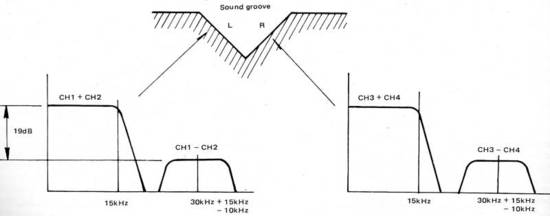
- An den Stellen, an denen hier 15kHz steht, steht bei Marantz 13kHz. Warum wohl ?

.
The four signals which are recorded are:
(CH1 + CH2) Left wall, audio signal
(CH1 - CH2) Left wall, frequency modulated signal
(CH3 + CH4) Right wall, audio signal
(CH3 - CH4) Right wall, frequency modulated signal
By providing circuitry, which can perform a simple algebraic operation on these signals, the four independent signals can be obtained.
1/2 [(CHI + CH2) + (CH1 - CH2)] = CH1
1/2 [(CHI + CH2) - (CHI - CH2)] = CH2
1/2 [(CH3 + CH4) + (CH3 - CH4)] = CH3
1/2 [(CH3 + CH4) - (CH3 - CH4)] = CH4
This is the principle of the CD-4 system. Not so difficult to understand, but it presented problems of an entirely new kind, which were sufficiently difficult to make some manufacturers, who investigated this kind of system discontinue their research.
JVC persevered, and in the course of their research, as well as developing the demodulator necessary to treat the FM component of the signal, was forced to develop a Noise Reduction System (ANRS), a new cartridge and stylus and an improved record material and cutting system.
Modulation (in drei Frequenzbänder unterteilt)
Throughout this discussion, for the sake of simplicity, the. modulated carrier which holds the difference signal is referred to as "frequency modulated". This is not entirely true; it is actually a combination of frequency modulated signals and phase modulated signals. Below 800Hz frequency modulation is used, from 800Hz to 6.000Hz phase modulation is used and then above 6.000Hz frequency modulation is again used. This takes full advantage of the nature of both these systems of modulation. There is reduced crosstalk and an improvement in the S/N in the mid, phase-modulated range and more linearity in the low and high frequency, frequency modulated, ranges.
PLL Demodulation (zur Trägerfrequenz Synchronisation)

The most critical element of the system is the demodulation of the frequency and phase modulated carrier, which holds the difference signals. There are several ways, in which this demodulation can be done, but the Phase Locked Loop (PLL) IC used in the CD-4 demodulator is most appropriate in this application.
The theory of PLL was discovered in the 1930s and has been used for detecting cosmic rays, measuring signals masked by noise and in other fields of telecommunication measurement. Its uses, however, were limited because of its size and complexity and it wasn't till the 1960s, that the PLL was perfected and compacted by NASA for use in space telecommunications.
The Phase Locked Loop is a feedback system consisting of a phase comparator (PC), a low pass filter (LPF) and a voltage controlled oscillator (VCO). The frequency of the VCO is synchronized with the incoming signal.
When the phase comparator detects a phase difference indicating a change in the frequency of the input signal, its output increases or decreases just enough to keep the VCO's frequency the same as the incoming frequency. This means that the voltage applied to the VCO is a function of the incoming frequency. If the VCO has a linear voltage to frequency relationship, and if the input to the PLL is a frequency modulated signal, then the voltage which must be applied to the VCO to correct its output to the phase comparator is the demodulated output required.
When there is no input signal to the PLL the VCO operates at 30kHz and there is no demodulator output. When an input signal with a frequency close to 30kHz is applied to the PLL, the VCO's frequency will follow the input signal and the signal which controls the VCO will be the demodulated signal.
The benefits of PLL demodulation are independent center frequency adjustment, independent bandwidth adjustment, high noise immunity, high selectivity and high frequency operation. Perhaps the most important in its application to CD-4 demodulation is the bandwidth adjustment which enables the carrier based difference signal to be detected without shattering distortion when the CD-4 record has been played back many times.
CD-4 Record Cutting (mit 1/3 Speed und anderen Tricks)

Several new techniques have been introduced into the record cutting process, all of them intended to facilitate playback and reduce the cost and complexity of playback equipment.
Cutting Equipment
The cutting equipment used at present is not able to cut the wide range of frequencies needed in the CD-4 system. Initially cutting was done at 1/2,7 (also etwa 1/3) of the normal cutting speed and this introduced a great number of complications; now cutting is done at 1/2 the normal cutting speed and this is a considerable amplification as the record cutters used throughout the audio industry have a 1/2 speed cutting mode. An additional complication that low speed cutting introduces is, that the various time constants needed in the CD-4 system must be scaled down accordingly.
Delay Circuit
In playback, the modulated signals must be picked up 40usec earlier than the corresponding sum signals. This is so that the demodulation process can be performed without altering the phase relationship between the sum and difference signals in playback. It is done by using a delay circuit in the sum signal's path; the length of this delay must be doubled to 80usec, if 1/2 speed cutting is being used.
Carrier Base Oscillator
A single master oscillator is used, to provide the base for the carrier on the two walls of the groove. This eliminates beats between the two signals, reduces crosstalk and minimizes distortion. Again the frequency of this oscillator must be scaled down when low speed cutting is being performed.
Carrier Level Controller
For their optimum, detection the level of the modulated signals must be different for different levels of the sum signal. The Carrier Level Controller compensates for this. The record cutter tape deck has two heads; as well as the main heads, there are also heads reading the tape slightly in advance. The signals from these heads are fed into a maximum envelope detector and from there into a level controller, which adjusts the level of the modulated difference signals before they are mixed with the sum signals.
Die "Neutrex" Vorverzerrung, noch ein Trick

The groove in the CD-4 system is complex and this presents a serious obstacle to the accurate tracing of the groove by the stylus as it must track both, the audio and modulated signals. If there was no kind of compensation, the stylus would tend to skate along the groove, tracking the imaginary waveform resulting from the mixture of audio and modulated signals, tracking neither accurately. The system developed by JVC is called Neutrex. It modifies both, the cutter waveform and the modulated signals, so that the correct signals are picked up in playback.
The effect of Neutrex is to improve channel separation by reducing interference between the sum and difference signals and the resultant distortion of the sum signals by minimizing fluctuations in the carrier level.
.

- Vergleich konisch elyptisch

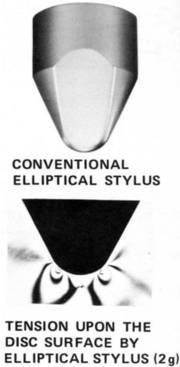
- Druckfläche elyptisch

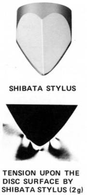
- Druckfläche Shibata

A new kind of cartridge and stylus
The CD-4 system needed a cartridge/stylus assembly with a wider frequency response than was available from those currently being produced. Conventional styluses were capable of a reasonably flat response up to a frequency of about 20kHz, and this is satisfactory in a conventional stereo system because the upper audible limit is 18kHz.
But, because the CD-4 uses a carrier based FM signal, which can hold necessary musical information up to 45,000Hz, research had to be undertaken to develop a new stylus.
Currently available styluses are classified as spherical or elliptical depending on the shape of the tip which comes into contact with the record groove: spherical styluses are most common. But the weakness of spherical styluses is, that they cannot follow the record groove accurately.
As can be seen from the diagram, when the groove changes in direction, it has a narrower effective width and the spherical stylus tip is forced up, so that it no longer traces the groove. To overcome this problem, an elliptical stylus was developed, that could trace the groove more accurately even when there were lateral oscillations.
But elliptical styluses have one serious drawback: the area of contact between the stylus and the groove is very much reduced. This means that for a given stylus pressure the force on the record is much greater and this accelerates record and stylus wear.
These were the conditions then: the new stylus had to have a larger contact area with the record groove than the conventional elliptical stylus and yet had to follow the groove more accurately.
The result was the SHIBATA stylus, called after the engineer, who led the development team. As can be seen from diagram, it has an entirely new shape which results in 4 times greater contact area than was possible before. This effectively doubles the mechanical resonance frequency, which in turn increases the frequency range.
The increase in the contact area by four times means, that for a given stylus pressure, the force on the record is reduced by the same amount; this increases record and stylus life by four times. And because the stylus has the ideal dimensions and shape, it follows the groove more accurately, decreasing waveform and phase distortion and increasing fidelity.
This increase does not apply to CD-4 records alone; when played back with a SHIBATA stylus, conventional 2-channel records have greater fidelity.
.
Anmerkung :
Leider wurde hier aus Marketinggründen eine wesentliche Eigenschaft des Vinyls unter- schlagen, die Elastizität (oder die "Weichheit") des gepressten Materials. Selbst der Laie erkennt, daß Schellackplatten beim Versuch einer Biegung fast sofort durchbrechen, die moderneren 45er und 33er Vinyl-Platten aber bis zu einem gewissen Grad biegsam sind.
Das konventionelle Vinyl ist insgesamt weniger hart bzw. recht elastisch. Das bedeuted aber, daß der Diamant - egal welchen Kalibers, die Rillenflanken mit zunehmender Frequenz immer mehr belastet, grob gesagt abrasiert. Für die CD-4 Platten soll angeblich härteres Vinyl verwendet werden.
Die Pressdrücke der Berührungsflächen sind zwar immer ähnlich hoch, je nach Auslenkung bzw. Amplitude des Signals, jedoch die Nadelnachgiebigkeit nimmt nach den hohen Frequenzen zu stark ab, das "Gummilager" ist immer weniger elastisch.
Die Vinyl Qualität oder Konsistenz wurde auf die Rillengeschwindigkeiten der 33er Platte (die mechanische Impedanz) dimensioniert und sollte bezüglich des Verschleißes der Rille sowie der Diamantspitze bis etwa 18.000 Hz funktionieren. Grenzfrequenzen von 45.000 Hz waren ursprünglich nie vorgesehen und die TED Bildplatte von 1972 hat ja gezeigt, wo die Verschleiß-Grenzen der mechanischen Abtastung solch hoher Frequenzen liegen.
.
.