Die englische Bedienungsanleitung des SME 3009 Tonarms

Das englische Handbüchlein ist sehr ausführlich und demonstriert hier ganz exemplarisch, auf welch schmalem Grad der Physik und der Elektronik die ganze analoge Schallplatten-Technik wandelt(e). Wenn Auflagekräfte im Variations- Bereich von 0,1 Pond (früher mal 0,1 Gramm) eingestellt werden müssen !!!, dann ist das doch sehr bezeichnend. Es ist mitnichten trivial, da einfach mal solche diffizilen Auflagekräfte einzustellen.
Wenn Sie dazu noch die Artikel über die Einflüsse der Resonanzen der Tonarme alleine mit ausgewählten MM oder MC Abtastern lesen, wird ihnen schummrig vor Augen. Und dann kommen noch die Kabel und Abtaster Kapazitäten hinzu, die nochmal entscheidenden Einfluß auf den Frequenzgang haben, selbst bei feinstem Accuphase Equipment - alles in Allem ist das überhaupt nicht zufriedenstellend.
.
Das Manual datiert irgendwo um 1960-1964
Darum dürfen wir über das enthaltene Eingenlob gepflegt hinwegsehen und feundlich lächeln. Bereits zu dieser Zeit war der SME 3009 und auch der 3012 nicht mehr "der feinste Tonarm der Welt". Die anderen Hersteller hatte sehr sehr schnell aufgeholt und ab 1967 kamen die Japaner ebenfalls mit solcher Edel-Mechanik auf den europäischen Markt. Bereits der Tonarm des DUAL 1219 stand der Qualität des SME 3009/3012 in nichts mehr nach. Alleine die Hochglanz-Optik war immer noch herausragend.

Modell 3009 Series II Improved
SME Model 3009 Series II Improved precision pickup arms combine latest design features with the same high quality engineering and finish that made their predecessors famous for more than a decade.
Each arm is meticulously built and tested and will meet its specification reliably through many years of service. Skilful design and choice of materials combine high mechanical strength with low inertia and friction ensuring full suitability for professional as well as domestic application.
Technically correct and aesthetically satisfying the SME has been called "The best pick-up arm in the world" and we believe you will find this to be true.
CONTENTS
.
4 Setting out
5 Fitting the Arm
6 Fitting the Cartridge
7 Model 3009/S2 Improved (detachable shell)
8 Audio Lead
9 Pillar Adjustment
10 Shell Adjustment
11 Tracking Adjustment
12 Balance Adjustment
13 Bias Adjustment
14 Operation
.
- Bild 101

- Bild 102

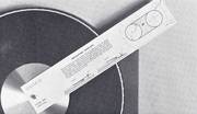
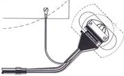
Setting out
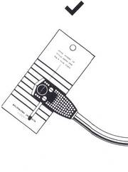
101 Establish the position for the bedplate with the mounting template.
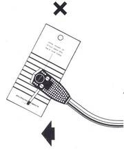
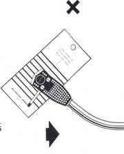
102 Where space is restricted the template may be rotated up to 70° off the radial position.
- Bild 103

- Bild 104

- Bild 106

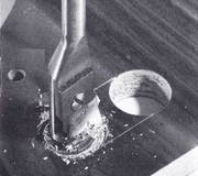
Fitting the arm
103 Drill and form the cut-out in accordance with the template. Ensure that it is large enough to clear the screening can completely. Drill the four A" (1.2 mm.) pilot holes for the wood-screws.
104 Screw down the bedplate with the four wood-screws.
(missing 105 Adjust the screws as shown.)
106 When the surface of the turntable is more than 1 5/8" (41mm.) above that on which the bedplate is mounted a spacer SME Accessory P.1 is required.
- Bild 107

- Bild 108

- Bild 109

- Bild 110

- Bild 111

Fitting the cartridge (in standard shell)
107 Fit the pin jacks to the cartridge terminals: White to left channel: Red to right channel: Blue to left ground: Green to right ground. Tails must never be soldered direct to the cartridge terminals.
108 Select screws of appropriate length. The top of the cartridge should lie snugly against the shell or as close to it as possible. The use of the finger lift is optional. Use spacers only if cartridge contours make it essential.
109 Fit the nuts.
110 Check that the cartridge ..js symmetrically in the shell. This is important.
111 Tighten the screws taking care to preserve (110)
- Bild 112

- Bild 113

- Bild 114

- Bild 115

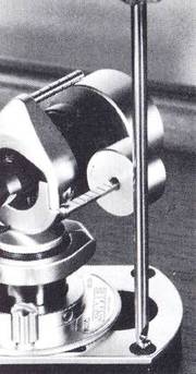
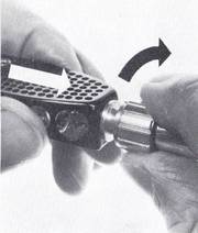
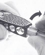
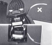
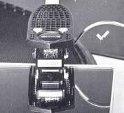
Model 3009 Serie II Improved (detachable shell)
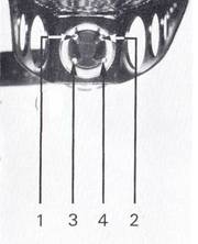
112 Fit the tails to the shell terminals: White (1) to left channel: Red (2) to right channel: Blue (3) to left ground: Green (4) to right ground. Fit the cartridge as detailed on Page 6.
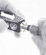
113 Insert the shell in the arm socket.
114 Press in to contact the thread.
115 Maintaining pressure, rotate the socket nut to draw the shell firmly home. Do not over-tighten.
- Bild 116

- Bild 117

- Bild 118

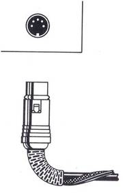
Audio Lead
116 Leads with 5-pole DIN plug make ground connection automatically.
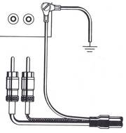
117 Leads with phono plugs (RCA / Conch) are coded White (L) for left channel and Red (R) for right channel. The ground wire should be connected to a terminal or screw on the amplifier chassis.
118 Insert the output plug into the output socket beneath the arm. Connect the ground wire to a suitable terminal or screw on the turntable chassis.
Note: There must be no other ground connections and the system must be connected to main ground by one path only, usually from the amplifier to the third pin of the mains. Additional paths to ground will increase hum.
- Bild 119

- Bild 120

- Bild 121

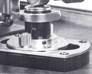
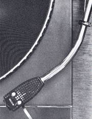
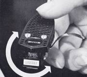
Pillar adjustment
119 Release the set screw in the base, to unlock the pillar.
120 Rotate the pillar to position the arm rest. The inner edge of the shell should be not more than 3" (76mm.) and not less than 12" (13mm.) from the edge of the turntable.
121 Set the pillar height so that the arm is parallel with the record surface when playing. Check that there is clearance between the track and the rubber mushroom of the lowering and raising control when the lever is in the down position. To increase clearance lower the pillar. Relock the base set screw.
Shell Adjustment
- Bild 122

- Bild 123

- Bild 124

Shell Adjustment
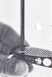
122 Place a small flat mirror on the turntable and rest the stylus on it.
123 If necessary hold the shell firmly close to the tone-arm and twist in the required direction with one hand whilst holding the arm firmly with the other. The stylus must be clear of{ mirror whilst this is done. Movemcc of the socket in the end of the tone-arm is limited by a detent screw.
124 Recheck with the mirror.
- Bild 125

- Bild 126

- Bild 127

- Bild 128

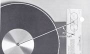
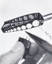
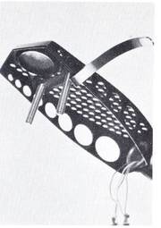
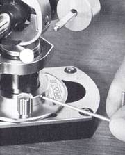
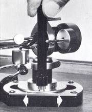
Tracking adjustment
125 Release the base clamp nuts with the plastic box spanner.
126 Place a record on the turntable
127 with the alignment protractor on
128 top of it. The large hole engages the record spindle with the stylus
base small one. Move the base on the bedplate until the cartridge and shell appear symmetrical with the protractor. Relock the base clamp nuts.


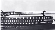
Balance adjustment
129 Position the rider weight so that its front coincides with the first division of the wayrod.
130 Place the arm in a state of equilibrium by rotating the balance weight in the required direction.
131 Release the set screw in the wayrod housing.
132 Divisions correspond to cartridge weights in grams. Adjust as required for your cartridge. The setting shov(
for 8 grams.
Relock the set screw.
133 Apply tracking force by advancing the rider weight along the wayrod. Each division travelled applies J (-25) gram tracking force at the stylus.
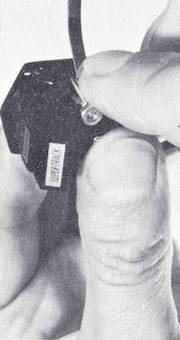
Bias adjustment


Bias adjustment
134 Fit the eye of the bias guide under the base clamp nut nearest to the turntable.
135-136 Thread the nylon through the guide pulley housing and pass the loop over the bias lever.
137 Place the nylon loop in the groove corresponding to the tracking force being used.
138 Position the bias guide so that the thread is at approximately 90° to the bias lever when the stylus is over the outer groove of a 12" record. Rotate the guide pulley housing to align it with the thread which must lie in the groove of the pulley.


Operation
139 With the control lever raised release the tone-arm from its rest.
140 Place the stylus over selected band on the record.
141 Move the control lever forward
142 allowing it to fall freely.
After playing, raise the control lever to lift the stylus from the record. Return the arm to its rest.
Nachsatz :
We hope these instructions have made the installation of your SME precision pick-up arm simple and straightforward. Care for it much as you would a camera. Do not attempt to take it to pieces.
Do not apply oil or other lubricant to any part of it. If you have a problem concerning its operation or repair write to the address overleaf. We provide quick and efficient service direct from the factory to any part of the world. In the first instance please write, do not send us the arm unless requested to do so.
The Company's policy is the continuous improvement of its products. We therefore reserve the right of any departure from illustration or specification herein that this may occasion.