Vorwort zu diesem nachgedruckten Artikel aus "RADIO & TV NEWS" vom Mai 1958
von Gert Redlich im Aug. 2016 - Wie bei uns hier in Deutschland auch - z.B. in der legendären Funk-Technik und der weltweit bekannten Funkschau, wurden sehr gerne Berichte und Artikel aus den Entwicklungsabteilungen der großen Hersteller "übernommen".
Nach mehreren guten Erfahrungen wurden die dann auch genauso abgedruckt. Hier haben wir aus einem amerikanischen Magzin "RADIO & TV NEWS" einen Artikel aus den Harrison (NJ) Röhren-Labors der berühmten RCA.
.

A Low-Cost Hi-Fi Amplifier
Simple 15-watt power amplifier uses new RCA beam power output tubes. - By LEONARD KAPLAN - "Electron Tube Div." der "Radio Corp. of America"
.
The new RCA-6913 Tube
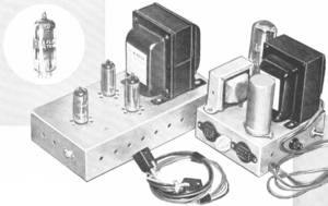
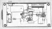
- Over-all views of the low-cost hi-fi amplifier along with its separate power supply. The new miniature beam power tube used is shown directly below.

THE new RCA-6913 beam power tube is a 9-pin miniature type developed specifically for use in the output stages of high-fidelity a.f. amplifier equipment. (Anmerkung : a.f. steht für "audio frequency")
The new tube has a 6.3-volt, 0.45-ampere heater, low screen-grid current requirements, and high plate and screen-grid voltage ratings which allow it to operate very efficiently in a variety of output circuits.
It is provided with specially designed grid structures and a basing arrangement which assure cool grid operation and freedom from grid emission.
.
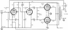
- Fig. 1. Complete schematic

This feature permits the use of much higher values of grid-No. 1 circuit resistance than are generally permissible for beam power tubes and gives the 6973 exceptionally high power sensitivity. Two 6973's, pentode connected, in a conventional push-pull class ABX output circuit can deliver as much as 24 watts of output power with very low harmonic distortion.
- Fig. 1. Complete schematic of the low-cost amplifier. This unit is not available in kit form but must be built by the home constructor from this circuit and parts.
.
A simple, low-cost high-fidelity amplifier

- Bottom view of the amplifier itself is shown here. Note the simplicity of the wiring and the absence of any crowding. Note also the use of the ground bus.

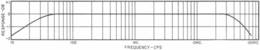
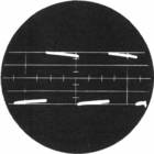
- Fig. 2. (A) Frequency response of the power amplifier taken at a reference level of 1.25 watts output.

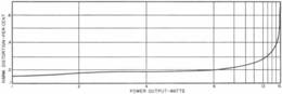
- Fig. 2. (B) Total harmonic distortion at various output powers.

The characteristics of the 6973 have made it possible to design a simple, low-cost high-fidelity amplifier using only three tubes and having performance characteristics indistinguishable from those of amplifiers having much more complex circuits, using more tubes, and costing many times as much. The new amplifier employs only standard, non-critical components, and does not contain any circuits, balancing adjustments, or other controls which might require the use of test equipment.
Anyone with a soldering iron and a modicum of construction experience should be able to assemble the unit and duplicate the results obtained in the laboratory.
- Anmerkung 1 : Wir schreiben 1958 und bislang hatten weltweit nur wenige Firmen in die theoretische und praktische Entwicklung von wirklichen Hifi-Verstärker investiert. Die Stereo Langspiel-platte wurde gerade erst propagiert und neu eingeführt. Bislang gab es auch nur wenige Audio-Quellen, die qualitativ überhaupt so gut waren wie Langspielplatten. Brauchbare Hifi taugliche Tonbandgeräte gab es zwar bereits, doch die Bänder waren zumeist mit eigenen Sprachaufnahmen oder UKW-Rundfunkmitschnitten gefüllt. Und auch nur wenige Firmen publizierten ihr Wissen - wie hier die RCA Laboratorien. Doch RCA war ja auch ein Röhrenhersteller und das war der große Unterschied zum Max Grundig mit seinen sehr umfangreichen genialen "Technischen Informationen" auf der anderen Seite der Erde.
.
- Anmerkung 2 : Schaun Sie sich mal den Frequenzgang an. Ob der getürkt ist oder real gemessen wurde, können wir nicht mehr nachvollziehen, denn diese Röhren dürften sehr sehr selten sein. Doch aus dem RCA Labs kam zu der Zeit sehr seriöses glaubhaftes Material. Der Maßstab in der Senkrechten ist 1dB pro Linie. Damit geht der Frequenzgang von nahezu 20Hz bis 50 Kilohertz und das ist für einen "LowCost-" Röhren-Verstärker eine Menge.
.
The Specs
Power Output: 15 watts continuous;
19 watts for short bursts
Sensitivity: .98 volt for 15 watts output
Frequency Response: 17 to 60,000 cps ±1db
Output Impedance: .65 ohm at 60 cps on 8-ohm tap
Total Harmonic Distortion .17% @ 1 watt output;
.19% @ 4 watts;
.2% @ 8 watts;
at 1000 cps: .4% @ 15 watts
Hum and Noise: 90 db below 15 watts (input shorted)
Hum and Noise: 75 db below 15 watts (input open)
(oben drüber :) Table 1. The performance characteristics of the amplifier described below.
.
Design Consideration
The initial specifications for the amplifier were:
.
- (1) It should be capable of reproducing everything the human ear can detect and, therefore, should have a frequency response flat within ±1db from 20 to 20,000 cps.
- (2) Total harmonic distortion at full output should be less than 0.5% so as to be virtually undetectable to even the most discriminating listener.
- (3) Because most authorities agree that a dynamic range of approximately 70db is necessary for high-fidelity reproduction it should have a power output of at least 15 watts so as to be capable of reproducing a range of 75db when used with speakers of average efficiency.
- (4) To assure good loudspeaker damping and permit operation with any type of loudspeaker system, including the new electrostatic types, it should have the lowest possible terminal impedance and the highest possible margin of stability. (Margin of stability is a term used to describe the ability of an amplifier to refrain from bursting into oscillation when used with a reactive load or when excited by signals having steep wave-fronts.)
.
Circuit Design

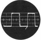
- Fig. 4. (A) Square-wave response at 20 cps. Some waveform tilt is shown.

- Fig. 4. (B) Square-wave response at 50 cps. A very slight tilt still remains.

- Fig. 4. (C) A 5000 cps square wave is shown here. Note the very slight ringing.

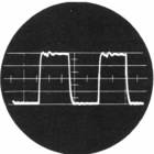
- Fig. 4. (D) This is a 10,000 cps square wave. The slight ringing has been spread out.

The circuit of the amplifier is shown in Fig. 1. The amplifier employs a pentode input stage, direct-coupled to a triode split-load-type phase inverter which, in turn, drives a pair of 6973's in push-pull class AB,.
The 6973's are pentode connected and are operated with fixed bias. The input and phase-inverter stages use the recently introduced RCA 6BH8, which contains a high-gain pentode and a medium-mu triode in one envelope.
The use of direct coupling between the input and phase-splitter stages minimizes phase shift at low frequencies and consequently increases the amount of inverse feedback that may be used without danger of low-frequency instability.
Because the plate voltage of the input stage determines the bias on the phase splitter the use of direct coupling can introduce certain difficulties, particularly in a high-gain, high-impedance circuit such as this one; that is, normal variations in the characteristics of the input pentode can produce wide variations in the operating point of the following triode.
This difficulty has been substantially overcome by obtaining the screen-grid voltage for the pentode from a high-impedance voltage divider. This voltage divider serves two purposes:
- (1) it prevents excessive screen-grid voltage from being applied to the tube during the warm-up period;
- (2) the large IR drop in the 1.5 megohm resistor tends to stabilize the screen-grid voltage against the effects of changes in tube characteristics.
Since the plate current and plate voltage of the pentode are highly dependent on the screen-grid voltage, the plate voltage also tends to stabilize from tube to tube so that any 6BH8 will perform well in the circuit.
One of the difficulties
One of the difficulties sometimes experienced with the split-load-type phase inverter is unequal high-frequency response in the two sections of the circuit due to the fact that the plate section has higher impedance to ground than the cathode section.
This difficulty has been minimized to a large degree in the new amplifier by use of a low-value load resistance (15,000 ohms) for each of the sections. The resulting high-frequency unbalance is negligible within the audiofrequency range and is less than 2db at 100,000 cps.
.
A class AB amplifier has several advantages
A class AB amplifier delivers highest efficiency and lowest distortion when operated with fixed bias. This method of operation has several advantages:
.
- (1) The quiescent currents are low and heavy currents are drawn only when power is being delivered to the load. Tube dissipation at normal signal levels is very small and, therefore, is favorable for long tube life.
- (2) The reactance of the cathode bypass capacitor normally used in a self-biased stage is eliminated. Practical sizes of cathode-bypass capacitors seldom provide adequate bypassing at very low audio frequencies. Their reactance increases rapidly as the frequency is lowered and causes a corresponding increase in output impedance which is detrimental to the stability of the amplifier when large amounts of feedback are employed.
- (3) The elimination of the self-bias resistor allows the bias to be independent of signal level and allows optimization of bias for lowest distortion.
.
Negative voltage feedback of 19.5db is applied around the entire amplifier to assure very low output impedance and minimize distortion. The small capacitors connected from the grid of the 6BH8 triode to ground and from the plate of one output tube (the lower one on the schematic) to the cathode of the input pentode increase the margin of stability substantially, as a glance at the photographs of the square-wave response in Fig. 4 will show.
The Power Supply
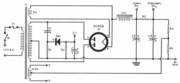
- Fig. 3. Diagram for separate power supply unit.

- A Underside view of the separate power I supply used with the amplifier. Selenium rectifier supplies fixed bias used.

Fixed-bias operation of the output stage requires that the plate supply have very good voltage regulation because the plate current varies considerably with the signal level. The circuit of the power supply is shown in Fig. 3.
It is a conventional choke-input system, and provides excellent regulation at low cost. The fixed bias voltage for the output stage is obtained from one-half of the high-voltage winding of the power transformer through a capacitance-resistance voltage divider and a 20-ma selenium rectifier.
The voltage divider allows the use of a selenium rectifier having a rating of only 130 volts r.m.s. The center tap of the heater-supply winding is connected to a resistive voltage divider across the output of the power-supply. The resulting 50-volt positive heater bias minimizes heater-cathode leakage and eliminates the need for hum-balancing adjustments.
Conclusion
The extent to which the original objectives have been achieved may be seen from the performance data shown in Figs. 2 and 4 and in Table 1. It can be seen that in every respect the amplifier exceeds the original specifications.
.
REFERENCES
.
- 1. Langford-Smith, F., ed.: "RCA Radiotron Designer's Handbook," Chapters 13, l4, 21
- 2. Olson, H. F.: "Elements of Acoustical Engineering," D. Van Nostrand Co., First Edition, 1947, pgs. 483-487
- 3. Schade, O. H.: "Beam Power Tubes," Proceedings of the IRE, February 1938
- 4. Williamson, D. T. N.: "Design of a High-Quality Amplifier," Wireless World, April-May 1947 and August 1949
- 5. Heacock, D. P. & Wissolik, R. A.: "Low-Noise Miniature Pentode for Audio-Amplifier Service," Tele-Tech, February, 1951
.